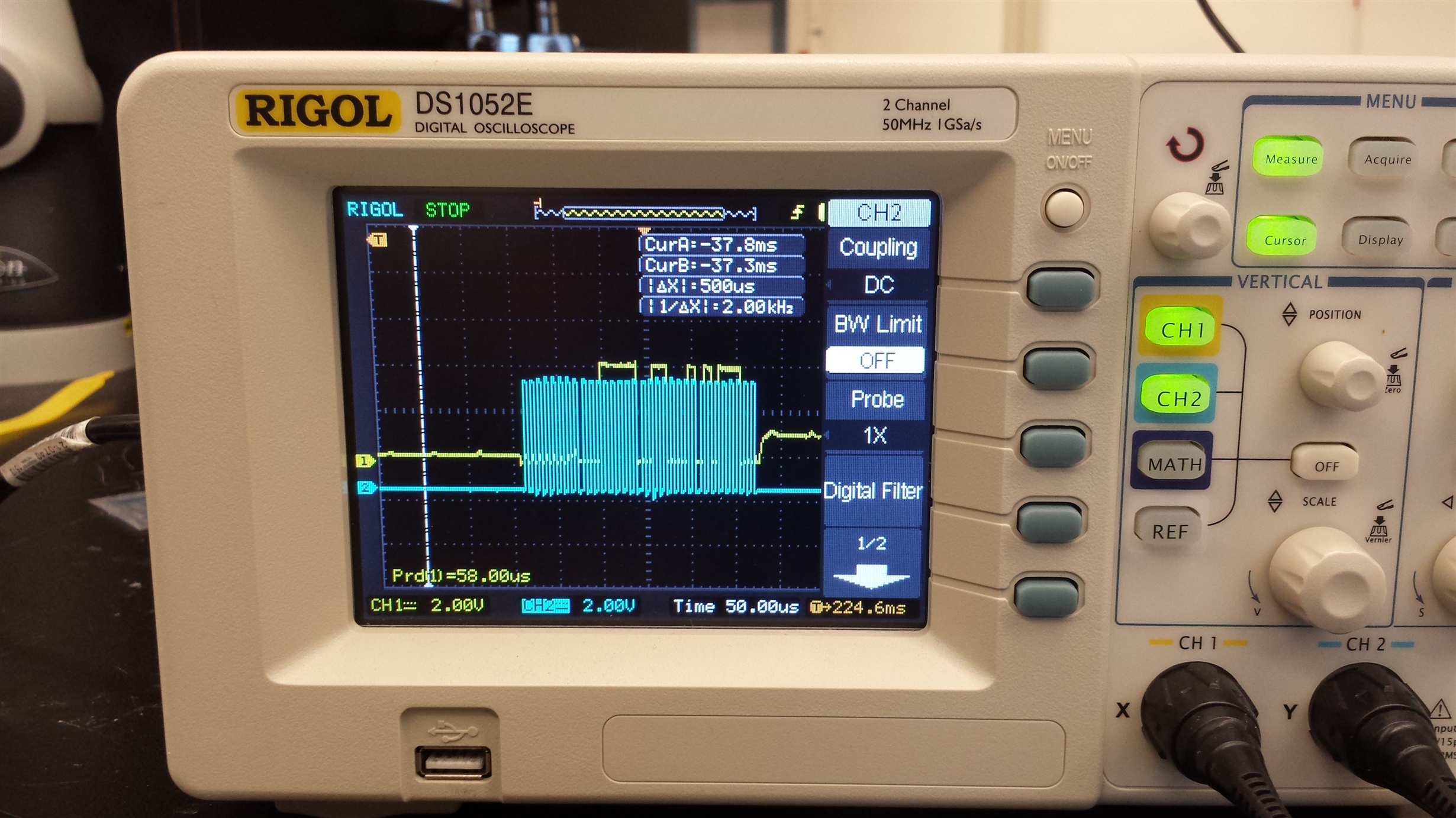
Hi,
I am trying to use the CC2640 as a SPI master, which interfaces to a 24-bit ADC.
The ADC chip requires customized packet format to setup its registers and read out ADC data.
I use the SimplePeripheral example as the baseline, and add the SPI driver according the notes here:
processors.wiki.ti.com/.../Adding_driver_cc2650
Then I did the following modifications to the NPI_TL driver coming along with the BLE_STACK V2.2.0:
1. set the macro of 'Board_SPI1_CSN' to 'IOID_25' in CC2650DK_7ID.h, so the there will be a 'CSN' signal generated on GPIO PIN #25
2. Modify the NPITLSPI_initializeTransport function in npi_tl_spi.c as follows:
void NPITLSPI_initializeTransport(Char *tRxBuf, Char *tTxBuf, npiCB_t npiCBack)
{
    SPI_Params spiParams;

    TransportRxBuf = tRxBuf;
    TransportTxBuf = tTxBuf;
    npiTransmitCB = npiCBack;

    // Configure SPI parameters
    SPI_Params_init(&spiParams);

    // Slave mode
    spiParams.mode = SPI_MASTER;
    spiParams.bitRate = SPI_SLAVE_BAUD_RATE;
    spiParams.frameFormat = SPI_POL0_PHA0; // 2016.Jun.30 : change to Mode (0,0) from Mode (1,1)
    spiParams.transferMode = SPI_MODE_CALLBACK;
    spiParams.transferCallbackFxn = NPITLSPI_CallBack;

    SPI_init(); // init first
    // Attempt to open SPI
    spiHandle = SPI_open(NPI_SPI_CONFIG, &spiParams);
    return;
}
Basically, I change the spiParams to adapt to the interface of my 24-bit ADC chip. And more importantly, I called the SPI_init(); before doing SPI_open();
Because I found if I don't init the SPI interface first, the interface can not be opened successfully.
3. The original TL SPI driver automatically adds a packet header to user data, in my case I have to disable this. So I modified the write function as follows:
uint16 NPITLSPI_writeTransport(uint16 len)
{
//    int16 i = 0;
    ICall_CSState key;

    key = ICall_enterCriticalSection();

    TransportTxBufLen = len;

    /*
     * 2016 July 1: the original code (commented out below) add
     * a packet header to the raw data.
     * This needs to be removed
     *
     *
    TransportTxBufLen = len + SPI_TX_FIELD_LEN;

    // Shift TX message two bytes to give room for SPI header
    for( i = ( TransportTxBufLen - 1 ) ; i >= 0 ; i-- )
    {
      TransportTxBuf[i + SPI_TX_HDR_LEN] = TransportTxBuf[i];
    }

    // Add header (including a zero padding byte required by the SPI driver)
    TransportTxBuf[SPI_TX_ZERO_PAD_INDEX] = 0x00;
    TransportTxBuf[SPI_TX_SOF_INDEX] = SPI_SOF;
    TransportTxBuf[SPI_TX_LEN_INDEX] = len;

    // Calculate and append FCS at end of Frame
    TransportTxBuf[TransportTxBufLen - 1] =
        NPITLSPI_calcFCS(&TransportTxBuf[SPI_TX_LEN_INDEX],len + 1);
     *
     * End of comment
     *
     */
    // Clear DMA Rx buffer and clear extra Tx buffer bytes to ensure clean buffer
    //    for next RX/TX
    memset(TransportRxBuf, 0, NPI_TL_BUF_SIZE);
    memset(&TransportTxBuf[TransportTxBufLen], 0, NPI_TL_BUF_SIZE - TransportTxBufLen);

    // set up the SPI Transaction
    spiTransaction.count = TransportTxBufLen; //NPI_TL_BUF_SIZE;
    spiTransaction.txBuf = TransportTxBuf;
    spiTransaction.rxBuf = TransportRxBuf;

    // Check to see if transport is successful. If not, reset TxBufLen to allow
    // another write to be processed
    if( ! SPI_transfer(spiHandle, &spiTransaction) )
    {
      TransportTxBufLen = 0;
    }

    ICall_leaveCriticalSection(key);

    return TransportTxBufLen;
}
So I commented out the code to add the packet header, and modified the length of the packet to be exactly the number of bytes in the transmit buffer instead of 270.
Then I modified the read back function as follows:
static void NPITLSPI_CallBack(SPI_Handle handle, SPI_Transaction  *objTransaction)
{
    uint8 i;
    uint16 readLen = 0;
    uint16 storeTxLen = TransportTxBufLen;

    // Check if a valid packet was found
    // SOF:

    /*
     * DO NOT Check packet format when communicate with MCP3901 chips
     * 2016 July 1
     *
    if ( TransportRxBuf[SPI_RX_SOF_INDEX] == SPI_SOF &&
            objTransaction->count)
    {
        // Length:
        readLen = TransportRxBuf[SPI_RX_LEN_INDEX];

        // FCS:
        if ( TransportRxBuf[readLen + SPI_RX_HDR_LEN] ==
                NPITLSPI_calcFCS(&TransportRxBuf[SPI_RX_LEN_INDEX],readLen + 1) )
        {
            // Message is valid. Shift bytes to remove header
            for( i = 0 ; i < readLen ; i++)
            {
                TransportRxBuf[i] = TransportRxBuf[i + SPI_RX_HDR_LEN];
            }
        }
        else
        {
            // Invalid FCS. Discard message
            readLen = 0;
        }
    }
    *
    *
    * End of Comment
	*/
     //All bytes in TxBuf must be sent by this point
    TransportTxBufLen = 0;
    RxActive = FALSE;

    readLen = objTransaction->count;
    SPI_Status stat = objTransaction->status;

    if ( npiTransmitCB )
    {
        npiTransmitCB(readLen,storeTxLen);
    }
}
I commented out the code the check the packet format, and return the raw data directly to the user.
4. I removed the definition of 'POWER_SAVING' so the NPI_FLOW_CTRL is disabled:
#ifndef NPI_FLOW_CTRL
#  ifdef POWER_SAVING
#    define NPI_FLOW_CTRL       1
#  else
#    define NPI_FLOW_CTRL       0
#  endif
This is because I don't need the MRDY and SRDY signals in my case
That is basically what I have done up to now. In the application code, I make sure to wait until each transaction is completed before issuing next request.
The problem is when I tried to read from the ADC chip, it always reads zero.
I have tested the ADC chip with Arduino, and everything works as expected. So I don't know what I have done wrong.
Can any body give me a hint on what to examine?


