This thread has been locked.

If you have a related question, please click the "Ask a related question" button in the top right corner. The newly created question will be automatically linked to this question.

CC2640 Custom Board (HID Advanced Remote) | Off - Chip OAD Feature | SPI External Flash | BIM Issue

Other Parts Discussed in Thread: CC2640, BLE-STACK, CC2650

Dear TI Team,

We developed a custom board using the CC2640 microcontroller.

We started using the last BLE-Stack (Version 2.2.0) and the HID Advanced Remote project in IAR IDE 7.70.1.

The major software features are already finished without any problem.

The debug process has been made by SmartRF06 EB but we also have the Debugger DevPack.

Meanwhile, in order to allow upgrade the firmware OTA, the 'Over-the-Air Download User's Guide for BLE-Stack Version 2.2.0' has been strictly followed as guide.

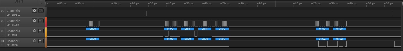
The board has an external flash (Macronix MX25V2006E), connected via SPI interface. Before proceed to the OAD feature addition, the SPI and ExtFlash drivers were added to the project. The driver was adapted to fit in our hardware. As can be seen in the following illustration, the SPI master (CC2640) and the SPI slave (MX25V2006E) are communicating as expected: the master successfully reads the flash information (manufacturer 0xC2 and device ID 0x12). So the hardware and the driver are both well functioning.

Next we open the BIM project (C:\ti\simplelink\ble_sdk_2_02_00_31\src\examples\util\bim_extflash\cc2640) and select the corresponding ReadOnly_LP configuration. Once the project is hard-coded for CC2650 LaunchPad, the following changes in the bsp.h header file were made:
// Board LED defines
#define BSP_IOID_LED_1          IOID_UNUSED
#define BSP_IOID_LED_2          IOID_UNUSED

// Board key defines
#define BSP_IOID_KEY_LEFT       IOID_UNUSED
#define BSP_IOID_KEY_RIGHT      IOID_UNUSED

// Board external flash defines
#define BSP_IOID_FLASH_CS       IOID_30
#define BSP_SPI_MOSI            IOID_19
#define BSP_SPI_MISO            IOID_18
#define BSP_SPI_CLK_FLASH       IOID_17

One more time, in order to evaluate the SPI communication, we put some breakpoints to debug the extFlashOpen function. Unfortunately the results are not the expected. The CC2640 can't read the flash information. However it's completely normal because according to the logic analyzer (see picture below), there is no clock signal. The SPI interface configuration remains unchanged:

  /* SPI configuration */
  SSIIntDisable(BLS_SPI_BASE, SSI_RXOR | SSI_RXFF | SSI_RXTO | SSI_TXFF);
  SSIIntClear(BLS_SPI_BASE, SSI_RXOR | SSI_RXTO);
  ROM_SSIConfigSetExpClk(BLS_SPI_BASE,
                         BLS_CPU_FREQ, /* CPU rate */
                         SSI_FRF_MOTO_MODE_0, /* frame format */
                         SSI_MODE_MASTER, /* mode */
                         bitRate, /* bit rate */
                         8); /* data size */
  ROM_IOCPinTypeSsiMaster(BLS_SPI_BASE, BSP_SPI_MISO, BSP_SPI_MOSI,
                          IOID_UNUSED /* csn */, clkPin);
  SSIEnable(BLS_SPI_BASE);

  {
    /* Get read of residual data from SSI port */
    uint32_t buf;

    while (SSIDataGetNonBlocking(BLS_SPI_BASE, &buf));
  }

Let me just notify that the bit rate is 1 MHz, exactly the same frequency used in the project mentioned above.

What can be the problem? Is there any pin configuration missing?

  • Assuming that you are using the same SPI driver in your project and in your BIM, I would verify that the SPI peripheral is being configured correctly in the BIM by comparing the SPI and PIN registers between the working case (your project) and the failing case (BIM). Something must be overwriting your configuration.
  • Hi Tim,

    In fact the SPI driver isn't the same.

    The SPI driver added to the main project has 4 files:

    • SPI.c and SPI.h are located at:

    C:\ti\tirtos_cc13xx_cc26xx_2_18_00_03\products\tidrivers_cc13xx_cc26xx_2_16_01_13\packages\ti\drivers

    • SPICC26XXDMA.c and SPICC26XXDMA.h are located at:

    C:\ti\tirtos_cc13xx_cc26xx_2_18_00_03\products\tidrivers_cc13xx_cc26xx_2_16_01_13\packages\ti\drivers\spi


    On the other hand, the SPI driver used by the BIM project has 2 files (bsp_spi.c and bsp_spi.h) located at:

    C:\ti\simplelink\ble_sdk_2_02_00_31\src\examples\util\bim_extflash\cc2640\board

    The second SPI driver appears more hard-coded (the instructions are closer to the hardware registers) than the first one which is based on the RTOS.

    Besides this issue, please clarify me the following... our main goal is to release a final product which can be upgradable downloading the new firmware over the air. The external flash is only used during this process, so the bootloader doesn't need to check any external image, am I right? And if am I right, the BIM_checkImages isn't really necessary, so if we define the NO_COPY preprocessor's directive, the bootloader will not communicate with the external flash and thus the issue previously mentioned will not be a problem anymore, correct?

    Can you provide some guidance?

  • After some efforts the source of problem was finally found.

    The SPI drivers are implemented in different ways but both work well, without any doubts.

    As previously mentioned the SmartRF06 EB (TI XDS100v3 USB Emulator) has been used as debugger.

    The Evaluation Board was connected to our custom board through the 10-pin ARM Cortex Debug Connector (P410) using a 10-pin cable. However there is a pin (pin 8) shared between the programming/debugging (TDI) and the serial interface (SCLK). Once this signal isn't necessary to program/debug the target considering the cJTAG (2-pin) configuration, in order to put the SPI interface working in both projects (main and BIM) was:

    1. Select the cJTAG (2-pin) interface in the IAR IDE;
    2. Connect only the necessary signals between the Evaluation Board (P409) and the target (custom board) using 5 wires: V_SENSE, GND, JTAG_TMS, JTAG_TCK and nRESET.

    And now both SPI drivers are functioning like a charm.