This thread has been locked.

If you have a related question, please click the "Ask a related question" button in the top right corner. The newly created question will be automatically linked to this question.

High power consumption in standby mode

Other Parts Discussed in Thread: CC2640, BLE-STACK, CC2540, TPS709, CC2650

Dear all,


I'm currentently working on a very low power project with CC2640.

I've noticed very high power consumption of the controller even in Standby-Mode.

In main(), I execute the following code: (I get the same results, when I use the standard standby power-policy)

  Power_init();
  Power_enablePolicy();
  Power_sleep(PowerCC26XX_STANDBY);

BIOS_start();

I expect the CC2640 go into Standby-mode consuming very low current around 1uA. But I measure a current around 1.8mA.

Are there any code references, I could use to enable Standby-mode and measure the current consumption?

How can I activate the Standby-mode?

Thanks in advance for your help.

  • Can you provide a bit more information regarding which TI-RTOS version you are using? Which IDE you are using(CCS or IAR)? Are you running with BLE stack?  Which HW are you using to develop CC2640(Launchpad or sensortag?)

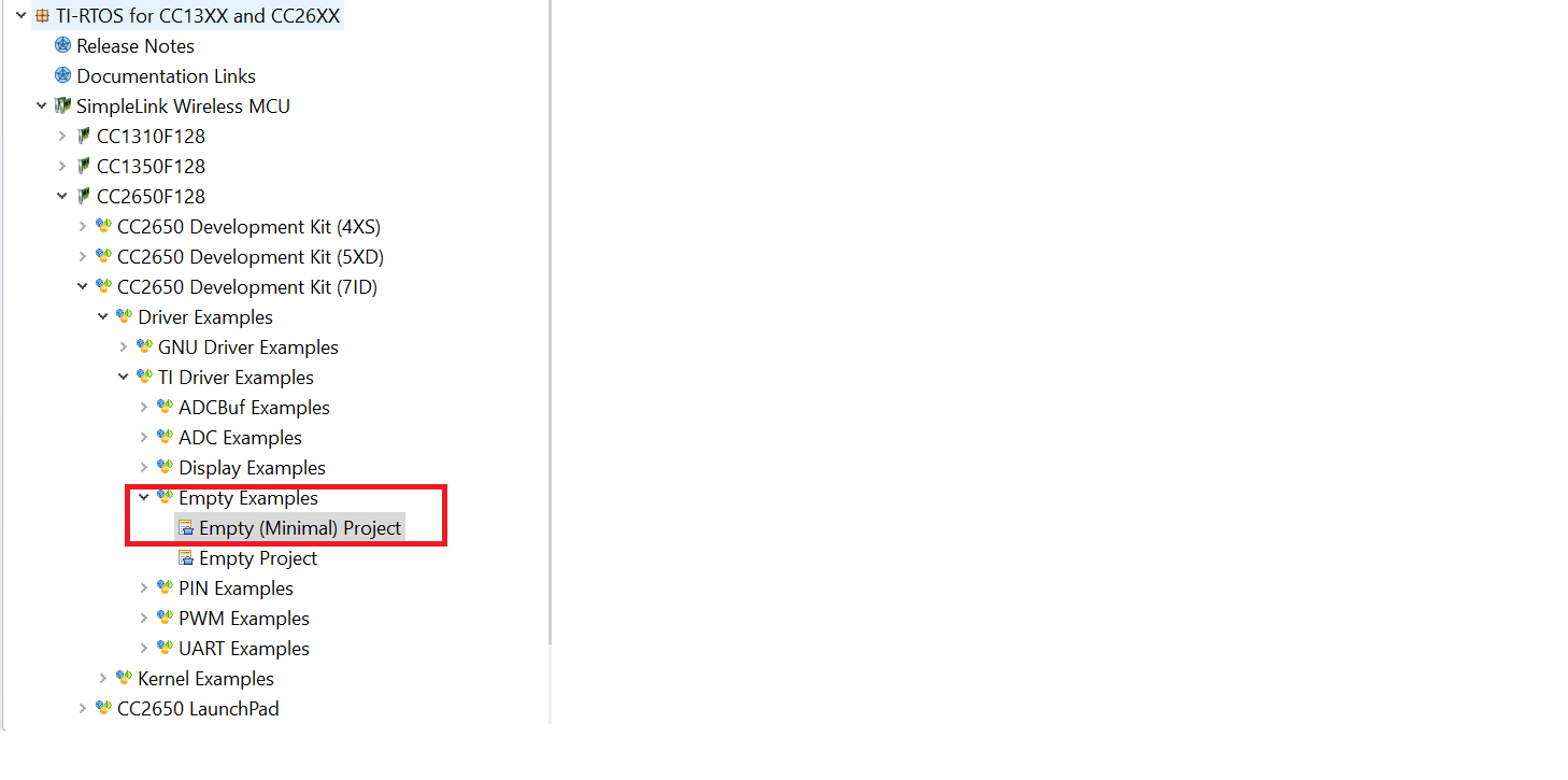
    The easiest way to do is using a TI-RTOS empty example project, then find the corresponding board file. In the main.c, you can comment out all the tasks. Then your program will look like this:

    /*
     *  ======== main ========
     */
    int main(void)
    {
    
        /* Call board init functions */
        Board_initGeneral();
    
        /* Start BIOS */
        BIOS_start();
    }
    

    You can also take a look at our application note regarding power consumption measuring here: 

    In this application note, we covered standby current profile, radio current and BLE related events current profile

  • Hi Christin,

    We are using CCS 6.1.2 for developing the application.
    RTOS-Version is 2.18. The application is running with BLE-Stack, Version 2_02_00_31

    We use the Innocom BM10_AN module with the CC2540.

    Thanks for your help!
    Peter
  • I guess "BM10_AN module with the CC2540. " is just typo. It looks like it's using our 7x7 package, so I will recommend you to do the following steps:

    1. import the project

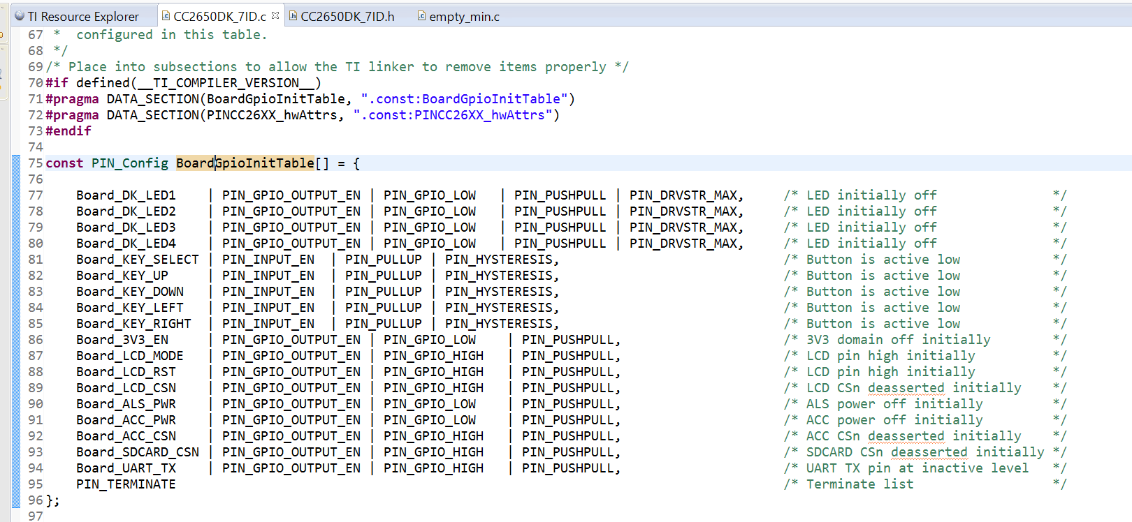
    2. Modify the Pin accordingly, since we don't have your HW, you will have to make sure all the IO connection to external component is configured properly.

    3. Modify the main.c according to the previous comment. 

    4. Program the device. 

  • Sorry, there was a typo: The BM10_AN has a CC2640.
  • Hi Christine,

    I removed all external components and flashed the sample-project according to your reply above.
    The result remains the same. The current consumption is still around 1.8mA.

    What else can we try?
    Regards,
    Peter
  • Can you see if you can execute from main.c and step through board init to just verify that the flashing process is successful?

    Also did you change all the pins to be no pull?
    Can you also take a picture of how you measure the current?
    Have you checked out the application note I attached?
  • I've set a breakpoint in main.c and could step through. So I think flashing is OK.

    Further, I've just changed all pins to Pull-up. With all pins set NOPULL, the board consumes 5.3mA.
    With all pins set to PULLDOWN, the board consumes ~1.6mA.

    I've checked the application note.

    As for the picture, I can describe.
    1) DC Power Supply, 7.30 V.
    GND connected directly to the boards GND
    + connected to the input of a Fluke 87 Multimeter
    2) + output of multimeter connected to the boards + input.
    3) Board has a linear voltage regulator for 3.8V. TI tps709.
    4) Innocomm-Module connected to the 3.8V output of the tps709.

    For me it seems like the module is not entering the standby-mode. Is there any possiblity of checking if the board really enters standby?

    Thanks for your help.
    Regards,
    Peter
  • Did you disconnect from the JTAG domain when you are performing the current measurement?

    In your custom board file, can you check if the power saving is on, which is declared in xxxxboard.c file.
  • Hi Christin,

    Yesterday, I found out that I have to remove the JTAG-debugger from my circuit and powercycle the board before the current measurment.
    This decreased the current to 313mA, which is much better, but still way of from specification in datasheet.

    Is there a way of somehow displaying in which power-saving mode the CPU is?

    How can I control if Sensor-Controller is on or off?
    How can I control if the Radio (BLE) is on or off?

    Thanks in advance for your help.
    Regards,
    Peter
  • I guess what you meant is 330uA, and it seems there is leakage current from the board. The only way to determine the power state CC2650 is on is measuring the power consumption. I guess you will have to contact the module vendor to help you find out where the current comes from. Since what has provided above works for most of the customers who use TI-EVM, I am not able to do more than what has been done.

    Regarding the control of different domain, all this is taken cared by TI-RTOS, as long as there is radio/sensor controller activities, then TI-RTOS will power that domain up. Once the tasks are done, the domain will be power off.