This thread has been locked.

If you have a related question, please click the "Ask a related question" button in the top right corner. The newly created question will be automatically linked to this question.

How to control slew rate when using SPI?

Other Parts Discussed in Thread: CC2650, CC2640

How to I change slew rate and drive strength settings for SPI? I’m getting poor signal integrity on my SPI output signals (SPI Clk and MOSI). I can improve the signal integrity by enabling the slow slew-rate (SLEW_RED) option in this register:
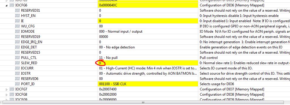
However, it looks like the slew rate & drive strength settings are hard-coded in the SPI_open() TI-RTOS function, and I don’t see a supported way to change this.

On a related note: Is there an IBIS model for the CC2650? This would help greatly with figuring out the proper way to configure the device to get good signal integrity

  • Hi Adam,

    Adam Dewhirst said:
    However, it looks like the slew rate & drive strength settings are hard-coded in the SPI_open() TI-RTOS function, and I don’t see a supported way to change this.

    Sort of. BLE example projects tend to include the SPI driver as source instead of linking in with the existing TI-RTOS libraries (for code footprint reasons). I suppose in your case, you'd probably want to modify it. You can add PIN_SLEWCTRL for CLK and MOSI in SPICC26XXDMA_initIO().

        /* Configure IOs */
        /* Build local list of pins, allocate through PIN driver and map HW ports */
        if (object->mode == SPI_SLAVE) {
          /* Configure IOs for slave mode */
          spiPinTable[i++] = hwAttrs->mosiPin | PIN_INPUT_EN;
          spiPinTable[i++] = hwAttrs->misoPin | PIN_GPIO_OUTPUT_EN | PIN_GPIO_LOW | PIN_PUSHPULL | PIN_INPUT_DIS | PIN_DRVSTR_MED;
          spiPinTable[i++] = hwAttrs->clkPin  | PIN_INPUT_EN;
          spiPinTable[i++] = object->csnPin   | PIN_INPUT_EN | PIN_PULLUP;
        }
        else {
          /* Configure IOs for master mode */
          spiPinTable[i++] = hwAttrs->mosiPin | PIN_GPIO_OUTPUT_EN | PIN_GPIO_LOW | PIN_PUSHPULL | PIN_INPUT_DIS | PIN_DRVSTR_MED; // <---HERE for example
          spiPinTable[i++] = hwAttrs->misoPin | PIN_INPUT_EN | PIN_PULLDOWN;
    
          /* Output low signal on SCLK until SPI module drives signal if clock polarity is configured to '0' */
          /* Output high signal on SCLK until SPI module drives signal if clock polarity is configured to '1' */
          if (object->frameFormat == SPI_POL0_PHA0 || object->frameFormat == SPI_POL0_PHA1) {
              spiPinTable[i++] = hwAttrs->clkPin | PIN_GPIO_OUTPUT_EN | PIN_GPIO_LOW | PIN_PUSHPULL | PIN_INPUT_DIS | PIN_DRVSTR_MED; 
          }

    I think the IBIS models might be in the design docs on the CC2650 product page.

    http://www.ti.com/product/CC2640/technicaldocuments#doctype12

  • Thanks. I don't see any CC2640 or CC2650 IBIS models on the product page or anywhere else though
  • Hi Adam, I just got word that we don't have any IBIS models for any CC26xx devices.