This thread has been locked.

If you have a related question, please click the "Ask a related question" button in the top right corner. The newly created question will be automatically linked to this question.

CC2541 certification for Korea

Other Parts Discussed in Thread: CC2541

Dear all
We have developed a product based on CC2541.
We successfully passed FCC and CE certifications, but we are facing some issues with Korea.
The laboratory in Korea wants to test dwell time, and they want us to allow the following :

BLE packets need to be sent with a duty cycle meaning not a continuous transmission of signals but a pulse like transmission of signals with a break time.
This is a test to measure the time bewteen signals during that break time.

In Korea, Bluetooth LE is considered to be hopping system(FHSS) and therefore Burst On-time per hop needs to be measured.

However, under FCC Part 15.247 or R&TTE 300 328, Bluetooth LE is considered DTS(Digital Transmission System) and therefore Burst On-time per hop does not need to be measured.

Only that with 300 328 test, when measuring E.I.R.P(Effective Isotropic Radiated Power), it is required to calculate with at least 10 or more bursts.

THUS, for 300 328 test, lab needs a setup or way to generate Burst. Actually Lab once have tested RFIC developed by TI, using RF Studio 7 program to generate bursts.

 With the program that is provided, it is not possible to transmit packet or bursts periodically(Periodic burst TX) and if the packet or burst is generated only in continuous wave, it does not satisfy requirements of KC requirements.

 Lab also tested RF Burst with normal sample but it does not provide option to test under long packet which is requied for the test. 

In our current firmware we implemented the different functions described in the wiki / FCC_ETSI_Test, but the lab said it is not enough.
We also asked them to use the product in normal mode (not test mode) to observe packets sent/received, but again they want us to be able to control the duty cycle.

They said they use Smart RF studio -> Packet TX successfully with their other customers to perform this missing test.
We are stuck with the above requirement from the Korean lab.

Any help would be greatly appreciated.
Thanks


  • Hi Jerome,

    Here is a link to the Smart RF Studio page. www.ti.com/.../smartrftm-studio

    You can download Smart RF Studio from the above link as well as find a Tutorial and Overview guide. What other assistance are you looking for?
  • Hi Jerome,

    Do you know why they need the ability to control the duty cycle? Isn´t the purpose of the testing to ensure that your specific application is within the requirements? Which would mean that your suggestion on using normal mode is correct?

    Cheers,
    Fredrik
  • Hi Rachel,
    Thanks for you answer.
    I already know where to download smartRF studio, and how to use it.

    Our problem is that we are using a custom firmware (based on simpleBLEperipheral), and a custom board.
    Thus, we cannot use smartRF Studio to test our board.

    We implemented the different functions described in the wiki / FCC_ETSI_Test, I can trigger these different tests modes using our custom firmware, this works but the Korean lab mentioned it is not enough, the lab needs a setup or way to generate Bursts, as mentioned in my original post.

    Do you have any recommendation to be able to control the duty cycle, or any other way to generate bursts ?
    Thanks

    Jerome 

  • Hi Fredrik,
    Thanks for you answer.

    Yes, they want to control our application is within the requirements for Korea.
    I indeed suggested to send/receive packets using our product in 'normal mode', but they mention the packets are sent continuously rather than in "burst" mode.
    This seems to be the reason why they cannot validate our product.
    Any idea to address this requirement ?

    Thanks
    Jerome
  • Hi Jerome,

    My recommendation would be SmartRF Studio. I do not understand why it can't be used with your HW, can you explain?

    Cheers,
    Fredrik

  • Because we use a custom firmware and custom board;
    So, as far as I understand we need to be able to connect the TI CC debugger to our board, and run "host test release" app rather dans a custom fw.
    Am I wrong ?
  • Hi Jerome,

    You do not need any FW on the device to use SmartRF Studio.

    Cheers,
    Fredrik
  • Thanks Fredrick

    In that case we will try to connect the TI CC debugger to our board so the lab can run smartRF studio to test our product.

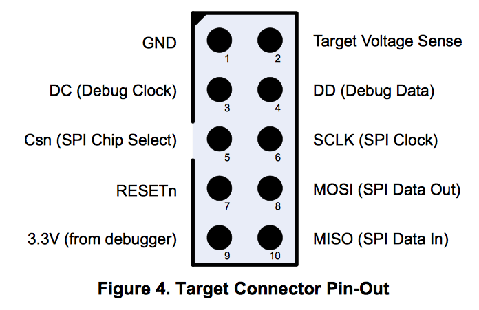
    One more question, which of the below signals are required to smartRF studio to communicate with our board ?
    We are using a CC2541 chipset on a Tiwi-UB1 module from LSR.

    I understand Target voltage is coming from our board so it should be connected (as well as GND).
    I guess DC/DD/RESETs should also be connected, what about the SPI signals (Csn, SCLK, MISO, MOSI), are these signals used by smartRF studio ?

    Thanks

  • HI Jerome,

    SPI is not required, so you have correctly listed the signals as VDD, GND, DC, DD and Reset.

    Cheers,
    Fredrik
  • Thanks for your prompt answers fredrik
    We will test and let you know if this works.

    Just to understand, is smartRF studio downloading a special firmware through the DD/DC lines when connected to the device ?
    Then writing special registers to access the different tests modes ?

    Jerome

  • SmartRF Studio downloads FW to RAM which controls the radio. It is only using the registers documented in the CC2541 User Guide.