This thread has been locked.

If you have a related question, please click the "Ask a related question" button in the top right corner. The newly created question will be automatically linked to this question.

Few CC2564MOD not working

Other Parts Discussed in Thread: CC2564MODN, CC2564

Hi

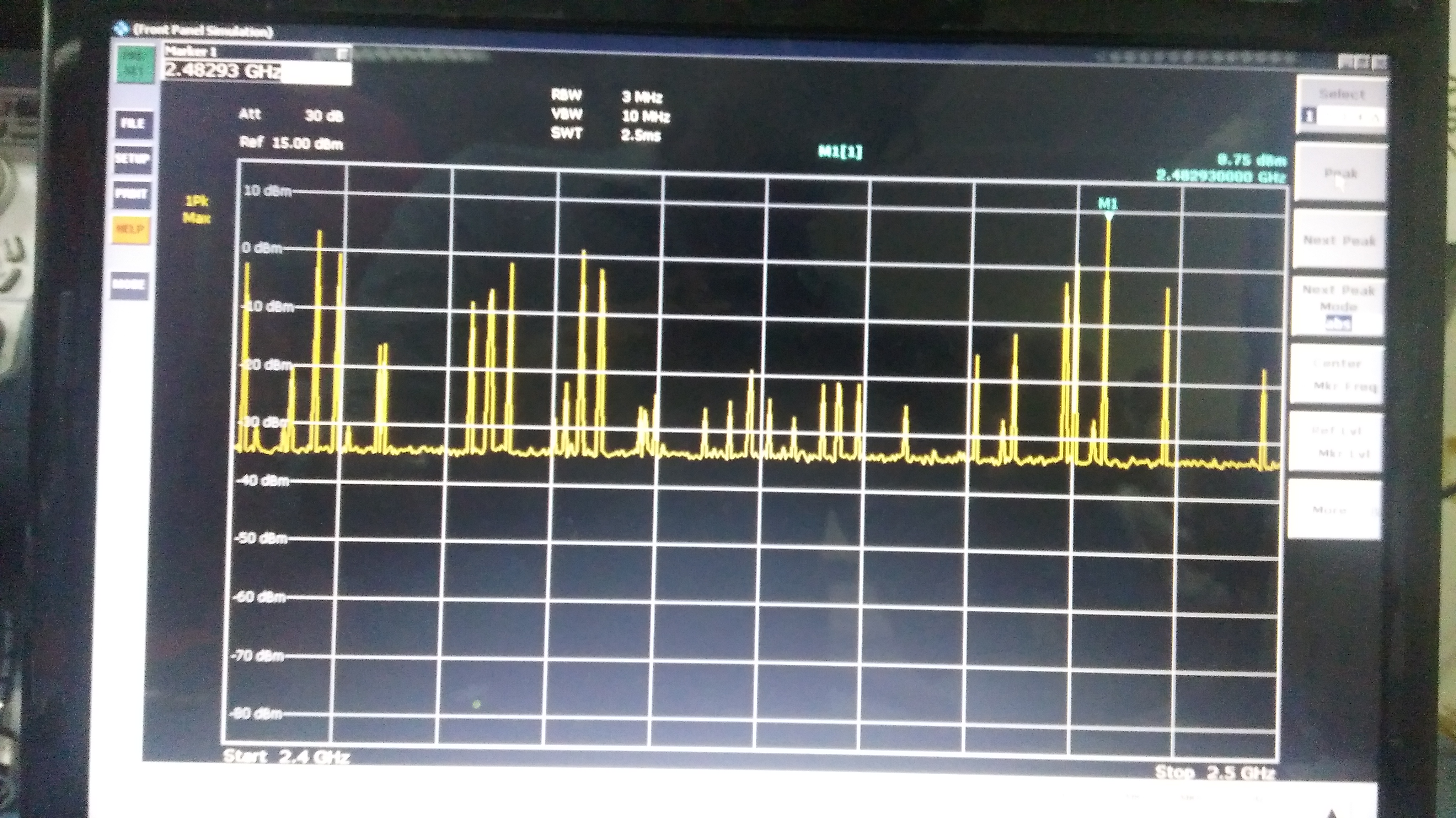
I am using CC2564MODN for one of my projects.Few of my modules are not working(Not working in the sense, i am unable to communicate). Not working modules are outputing power similar to working modules. On a spectrum analyser, i found the spectrum of these two as different. Attached below are the spectrum images of both.

1. Working Module Spectrum
2. Non Working module spectrum
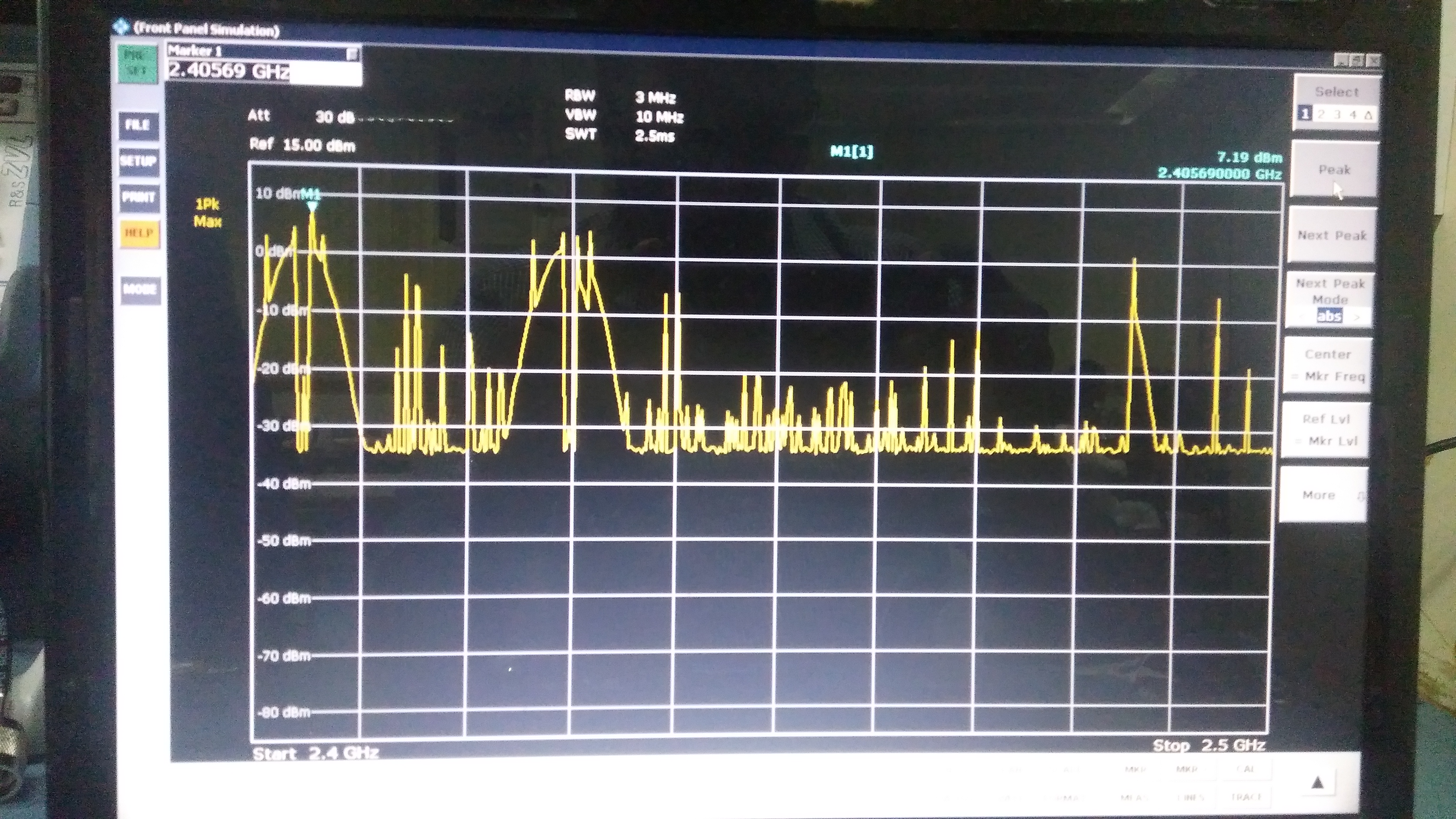
What might be the reasons for this?

Regards

Riyaz R

  • Hi,
    Your query has been assigned to our H/W expert.
    Please expect a follow-up response.
    BR,
    Eyal
  • Hi Riyaz,

    There is a good chance this could be related to the layout. If you'd like I can review the layout and offer any suggestions as to what could be going on. Feel free to message me or comment with your email and I will get in contact with you.

    Thanks,
    Mitchell
  • Hi Mitchell Kinkeade

    Thanks for the support.

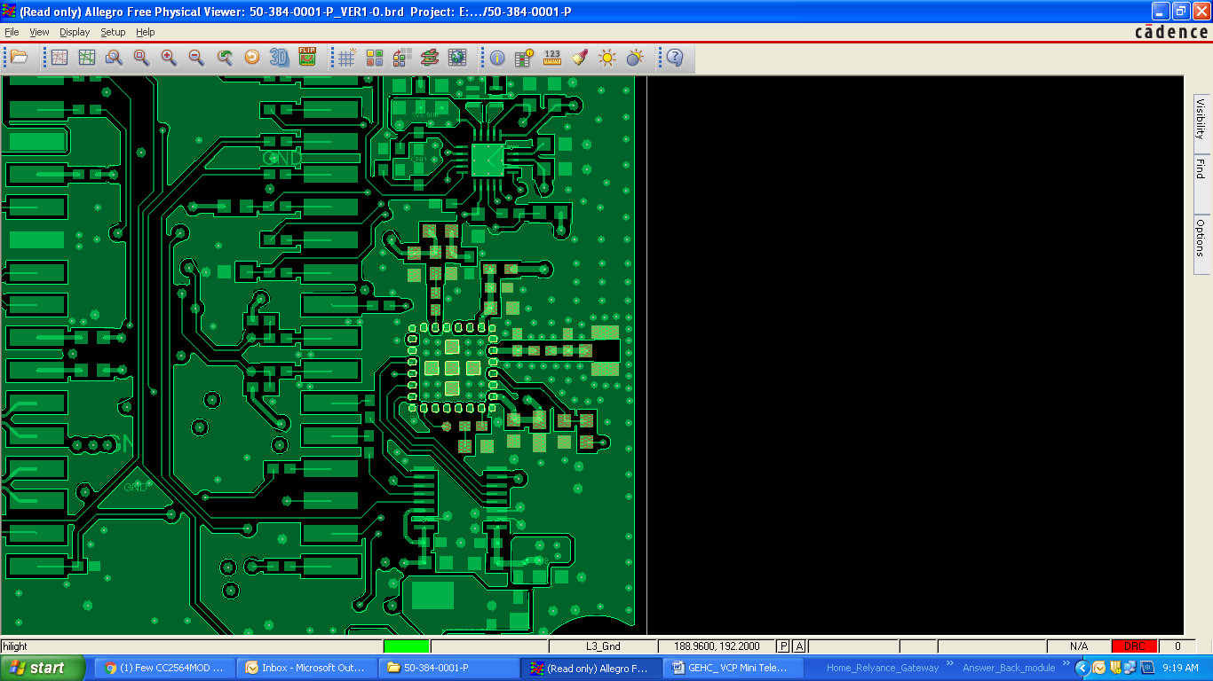
    Please find attched the screen shot of layout with CC2654MODN and associated circuitry highlighted.

    Regards 

    Riyaz 

  • Hi Riyaz,

    From what I can see in the above image, the layout looks okay. Is there any way you can share a schematic capture of the RF path on the CC2654MODN? I'm curious as to what components and chip antenna you are using. Also, is the trace width on that path matched to 50ohm?

    Can you provide some more details on what steps you've taken to troubleshoot the device. How many boards are working and how many are failing? If you haven't already, I'd suggest walking through the CC256X Production Line Testing Guide found here

    Thanks,

    Mitchell

  • Hi Mitchell

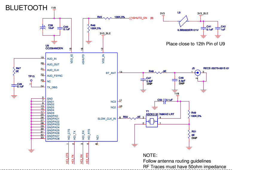
    Attached is the schematic view 

    Out of 30 prototypes, 15 failed.

    Trace width match to 50Ohm impedance performed.

    We are using a flex PCB antenna not a chip antenna.

    Please go through the schematic and share your views.

    Regards

    Riyaz

  • Hi Riyaz,

    Thank you for sharing. I think the issue might be coming from the RF path, as there is no LC filter prior to the antenna connector. Adding in a matching filter could help eliminate the noise you are seeing on the spectrum analyzer.

    The reference schematic found inside the CC2564 datasheet (page 29) uses a chip antenna and has a LC filter in place to balance the antenna.

    You might be able to replace R48 with an 9.1uH inductor, or similar, and see if that provides any improvements.

    Right now, this is my initial assessment; however, I'm going to loop in some experts to offer up their suggestions as well.

    Thanks,
    Mitchell
  • Hi Riyaz,

    I am the Lead HW expert working with the CC2564 family of devices. It is hard to say the root cause of the issue. It would be best if we could review the schematic, BOM and layout. If you would like us to review, please send the files via e-mail to rizwan.murji@ti.com. Please send the Gerber files and the design files of the layout if you can. We can review Altium, Mentor and Cadence layout design files.

    I will go ahead an close this thread for now. If you need anything else you can e-mail or re-open.

    Thanks,
    Riz