This thread has been locked.

If you have a related question, please click the "Ask a related question" button in the top right corner. The newly created question will be automatically linked to this question.

CC2541: Advertising Mode Vs Connection mode

Part Number: CC2541
Other Parts Discussed in Thread: CC2640, CC2640R2F,

Hi,

   I have a small doubt regarding advertising and connection mode.Can anyone tell me which mode is better as compare to power saving?

1.If my device is completely advertising not going in connected state.Is it will consume more power or less power as compare to connection mode?

Thanks in advance !!

  • Hello Anshul,
    That depends on the interval or connection settings. There is no simple answer I am afraid. You should find out what the application requires and study the following app note which also includes some spread sheets you can use:
    AN092 -- Measuring Bluetooth Low Energy Power Consumption
    www.ti.com/.../litabsmultiplefilelist.tsp

    The CC2640/CC2640R2F is our latest device with even lower power. If you pan to use that instead you can play around with the power-calculator:
    www.ti.com/.../power-calculator.page

    What exactly are you trying to achieve in your application?
  • Hello Eirik,
    Actually I already gone through this application note.Simply I developed a customized board using Texas KeyFob and I am using the same application(KeyFob) provided by Texas with minimal no. of changes as required.My ultimate goal is to read GPIO status dynamically and send it to my android application,High alert,Low alert.
    To do these jobs there are two ways:
    1.Advertising mode: In advertising mode I can send my GPIO status through advertising packet.And for High or Low Alert i need a connection.
    2.Connection mode: This is normal mode as default application is doing.
    Now my doubt is Which mode is best as compare to power saving.
    Is it true if my device will be in advertising mode indefinitely,MCU will not be able to go in Sleep mode where it consume less current(0.001uA)?
    And in Connected state max time device will be in sleeping state and MCU will wake up only when some interrupt will come?
    If it is true then connected mode will be power saving. Is it??
    Please correct me if I am wrong !!
  • Hello Anshul,
    CC2541 will enter sleep (PM2) in between advertisement events in the same manner as it will between connection events while in a connected state.
  • Thanks for the information Eirik, Can you please clear difference between connection interval and advertising interval?

    Is both r same or any difference??
  • Hello Anshul,
    advertising interval is the time between each advertisement event and connection interval is the time between each connection event (When Master and Slave communicate in a connection). As you seem to be unfamiliar with the basic concepts I recommend you to google some tutorials or perhaps check out a book or two about Bluetooth low energy. Here is one example:
    www.amazon.com/.../ref=sr_1_1

    Also for our latest family of devices, CC26xx, we have many great tutorials in Simplelink Academy:
    software-dl.ti.com/.../overview.html
  • Thanks Eirik !!
  • Hi Eirik,

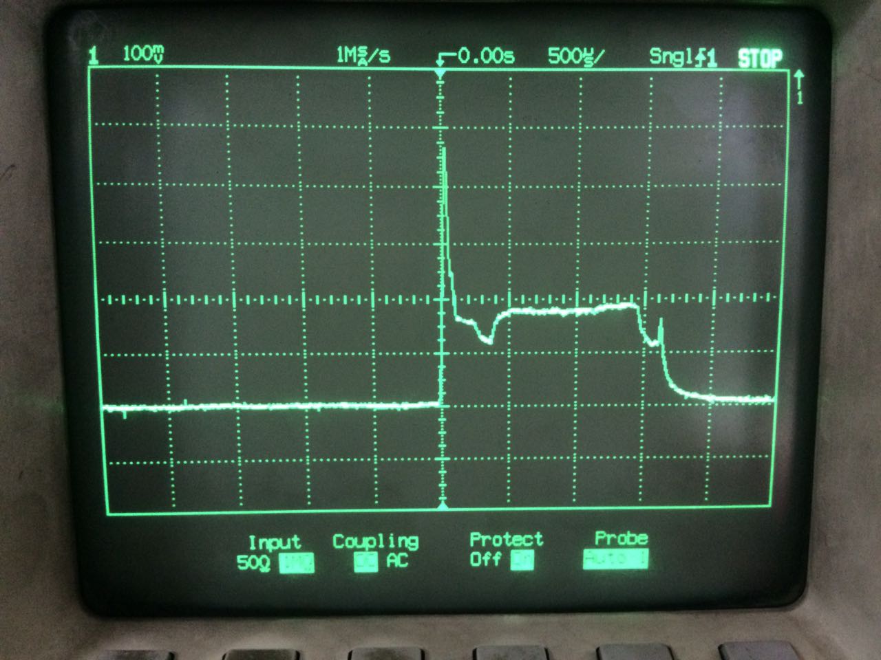
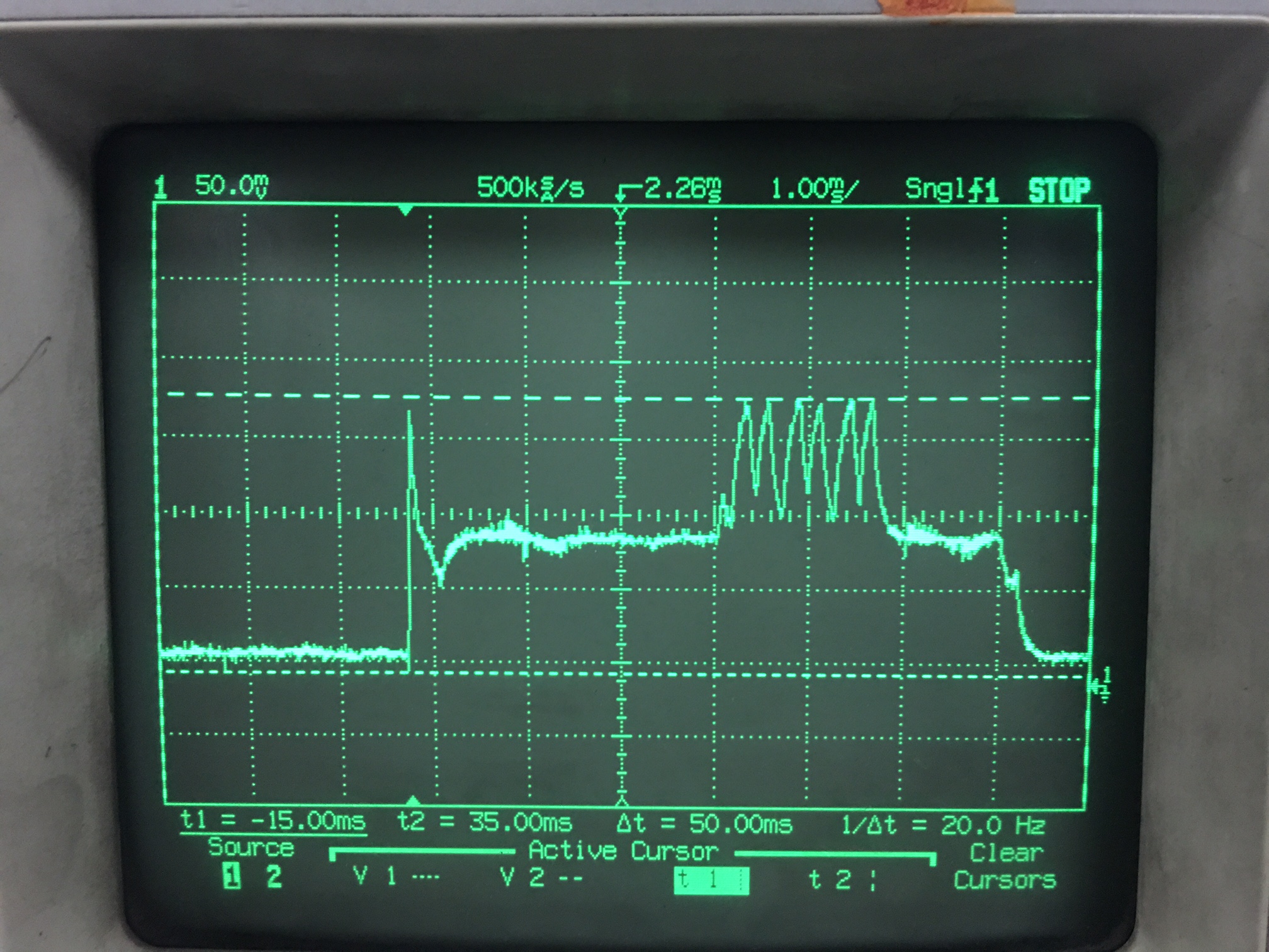
           I was testing my device in advertising mode and capture a graph that is completely different from Texas Keyfob graph. Both boards are advertising with 10sec interval.

    For Ti board i got this graph.

    For our custom board we got this graph with same advertising interval.

    If we compare both the graphs voltage level is same but MCU wake up time is different.

    Will you Please help me to conclude what may be the possible reason behind this??

    Thanks,

    Anshul

  • Hello Anshul,
    Are you worried about different timing or the different shape of the current measurement plots? Difference in decoupling and board layout will affect the shape of your current measurement. The advertisement interval will always have an added pseudo-random delay in the range of 0-10 ms to avoid continued collisions over time. For example when different advertisers start at the same time with the same adv. interval. they could end up interfering with each other for quite some time if it where not for this random delay.
  • Hi Eirik,
    Actually I am worried for both the reasons,you are right I just confirmed with system team that they removed decoupling capacitor from board.Our custom board is not able to give enough battery back its battery going to drain in 3 to 4 days only so we thought may be some drop due to these decoupling capacitors.
    My concern is can we reduce this transmitting time which is more in our graph as compare to TI graph?
    As my board is not able to give enough battery back up as compare to TI board,Can you suggest me some possible reasons where should i look?
    Thanks,
    Anshul
  • Your x-axis resolution on the scope is different for the two plots (500 us and 2 ms). Its the other way around. As long as you follow our ref. design it should work.
  • Thanks for the information Eirik !!
  •  Hi Eirik,

    Is there any Ti document or excel sheet  to calculate power consumption in advertising mode only. As I was going through Texas application note for Power calculation but it is only for connection state. when my board is advertising it is getting graph like this.But In texas document nowhere mentioned graph like this.
    Now problem is how to calculate power consumption.


    Thanks,

    Anshul

  • Hello Anshul,
    You will need to modify the excel calculation sheet manually.
  • But my confusion is In Texas sheet they used connection interval as 1000ms but if I am advertising only then no use of connection interval and In above graph we r getting total 6 spikes as compared to connection graph where only 2 spikes (Tx/Rx).That means total calculation will get changed.
  • Hi Eirik,
    I am using Texas KeyFob as a evaluation board.Can I get the PCB details(Like material used,Layering) of Key Fob board?
    I got PCB layout but these material details are not mentioned anywhere.

    Thanks,
    Anshul
  • Download the design files and then open the Readme.txt:

    PCB DESCRIPTION:4 LAYER PCB 1.6 MM
    Copper 1 35 um
    Dielectric 1-2 0.35 mm (e.g. 2x Prepreg 7628 AT05 47% Resin)
    Copper 2 18 um
    Dielectric 2-3 0.76 mm (4 x 7628M 43% Resin)
    Copper 3 18 um
    Dielectric 3-4 0.35 mm (e.g. 2x Prepreg 7628 AT05 47% Resin)
    Copper 4 35 um

    DE104iML or equivalent substrate (Resin contents around 45%, which gives Er=4.42@2.4GHz, TanD=0.016)
    Dimensions in mil (0.001 inch)
    DOUBLE SIDE SOLDER MASK,
    DOUBLE SIDE SILKSCREEN,
    8 MIL MIN TRACE WIDTH AND 8 MIL MIN ISOLATION.

  • Hi Eirik,

     Is this OAD service is not supported by android platform.I was trying to use Texas sensortag Android application but its going to crash.Its working fine with Ios Application.Is there any need to add some service or something to my code??

    I was looking into forum so find out that some connection control service is missing.Is it needed to add it to my code?


    Thanks,

    Anshul