This thread has been locked.

If you have a related question, please click the "Ask a related question" button in the top right corner. The newly created question will be automatically linked to this question.

cc2650

Other Parts Discussed in Thread: CC2640, CC2650

Hello All,

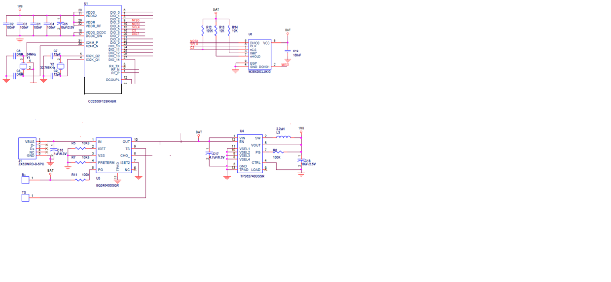
I have used external regulator TPS62740DSSR with  CC2650F128RHBR so supply voltage to controller is 1.8V. I want to add flash memory so thought to use  W25X40CLUXIG.

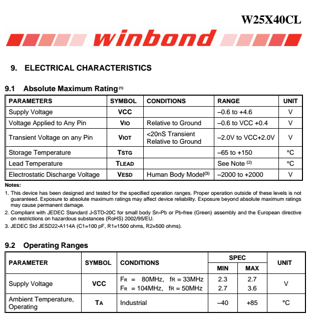
But supply voltage to flash memory is battery voltage i have given which is 3.2V. I have attached schematic will this communication work as i have doubt there is voltage difference between controller side (1.8V) and flash memory side (3.2V).

Also  I want to know what voltage will be there at controller pin no 9,10,15,16  if we use external voltage regulator and internal voltage regulator.

  • Hi Ap,

    The IO voltage will be the same as the supply voltage, so with the configuration above the logic levels on the IOs will be 1.8 V. The external flash will pull the lines to battery voltage and thus violate the maximum ratings of the CC2640.

    It is possible to run half of the IOs at a different voltage level by connecting VDDS2 to, in this case, the battery voltage. You must then ensure the IOs used by the flash device are supplied from VDDS2. Refer to section 11.10.2 in the TRM for details. www.ti.com/lit/pdf/swcu117

    Cheers,
    Fredrik
  • Hello Fredrik,

    As per TI reference  if we are using external voltage regulator then controller should work on 1.8V itself .

    flash whatever i have used has operating range as shown below in screenshot. so i have doubt  it solve my problem by using VDDS2 

    Thanks and Regards.

    Ap

  • Hello Fredrik,

    As used in  CC2650 launch pad if we use MX25R8035F Flash memory  operating voltage  is (1.6-3.6V ).

    so it will solve my issue I guess  as i can keep same voltage 1.8V both side. 

    Please suggest reliable change.

    Thanks and Regards,

    Ap