Part Number: CC2640
Hello to all,
Currently we have design BLE with use of CC2640.
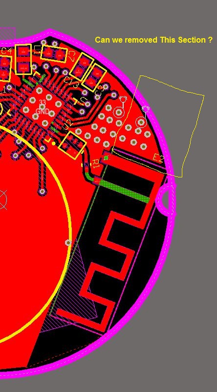
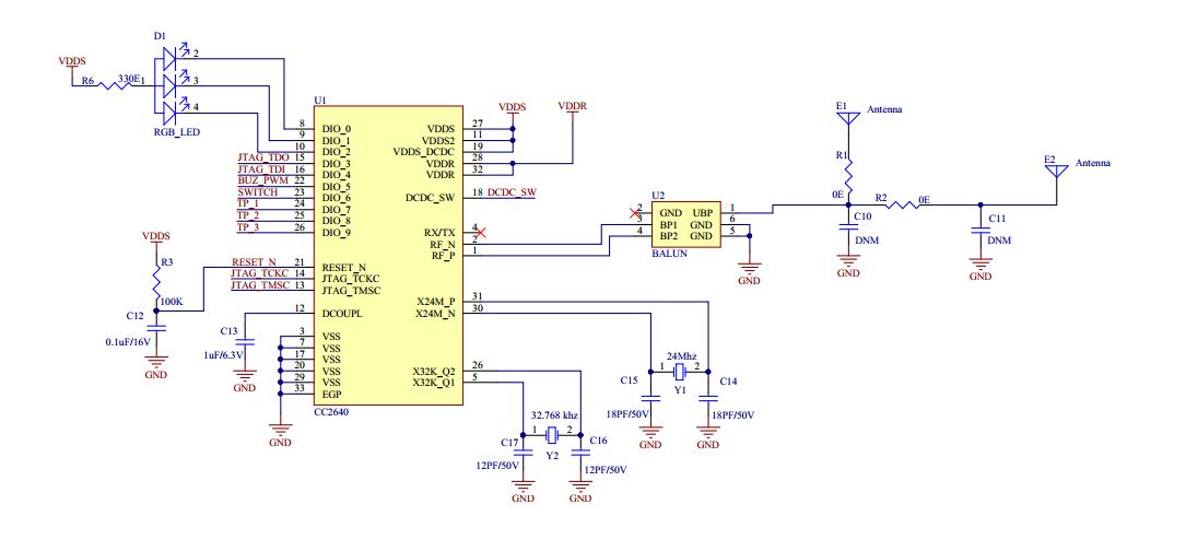
Here attached cc2640 connections schematic so kindly review it give suggestion if its needed.
E1 :- U.F.L. connector
E2 :- 2450at18d0100E
U2:- 2450BM14G0011T
Part Number: CC2640
Hello to all,
Currently we have design BLE with use of CC2640.
Here attached cc2640 connections schematic so kindly review it give suggestion if its needed.
E1 :- U.F.L. connector
E2 :- 2450at18d0100E
U2:- 2450BM14G0011T