This thread has been locked.

If you have a related question, please click the "Ask a related question" button in the top right corner. The newly created question will be automatically linked to this question.

RTOS/CC2640R2F: I2C sensor

Part Number: CC2640R2F

Tool/software: TI-RTOS

Hey, so I'm using this Launch pad http://www.ti.com/tool/launchxl-cc2640r2. I'm currently working with sensor composer studio but can't appear to get an output reading on the I2C Temp & humidity sensor I'm using https://www.silabs.com/documents/public/data-sheets/Si7021-A20.pdf. I've read several forums and Altered the clock frequency and stretch time out to no avail. I have also altered the code several times but the output graph while testing just flat lined bar i2cStatus the outputs a 1 value. Here is my code below. I'd appreciate the help, thanks. 

i2cStart();


    i2cRepeatedStart();
   i2cTx(I2C_OP_READ|Temp_NHM);//0xf3
    i2cRxAck(output.Temp);
    
    
     i2cTx(I2C_OP_READ|Hum_NHM);//0xf5
    i2cRxAck(output.Hum);

i2cStop();

// Read the result after 100 milliseconds + a 20% margin
evhSetupTimerTrigger(0, 120, 2);

// Schedule the next execution
fwScheduleTask(400);

////////////////////////////////////////////////////////////////////////////////////////////////////////////////////////

  • Hi Rory,

    Do you have external pull-up resistors for SCL and SDA? Do you have a logic analyzer you can connect on the i2c pins?

    Regards,

    Klas
  • Hey Klas,

    I do have pull up resistors. I might be able to get a logic analyzer sometime next week. The reason I thought it could be an issue with the code is that I connected the SDA and SCL pins to an oscilloscope and it didn't pick up any voltage remotely like I was expecting. I'm concerned that it could be an issue with the board.
  • Hi Rory,

    I just tested your code 

    i2cStart();
     
    i2cRepeatedStart();
    i2cTx(0xF3 | I2C_OP_READ);
    i2cRxAck(output.Temp);
           
    i2cTx(0xF5 | I2C_OP_READ);
    i2cRxAck(output.Hum);
    
    i2cStop();

    and i can indeed see activity on the i2c pins using a logic analyzer. I don't have the sensor you're using, so the program still might not work. If you could get your hands on an analyzer or an oscilloscope that would be helpful!

    Regards,

    Klas 

  • Rory,

    I realized you already have an oscilloscope. Are you able to connect and run the code without errors in the Task Testing view?

    Regards,

    Klas
  • Hi ,


    I'm 90% certain its an issue with the sensor now, I ran a different program with the same IO pins and they appear to be functioning fully. I have ordered a new sensor attached to a breakout board. I should have it tomorrow or Thursday, I'll give you an update then.

    Thanks Klas!
  • Hi Rory,

    You could also try the sensor with the i2c driver using the main processor. It offers a little more opportunity to debug.

    Regards,

    Klas

  • Hi Klas, 

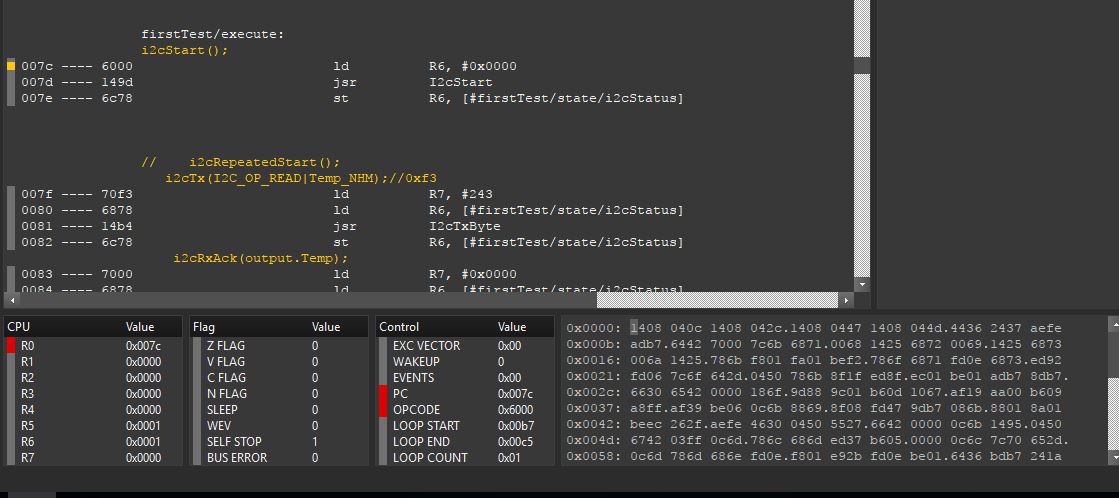
    I'm using  new sensor now. An SI-7021 on a spark fun brake out board. I've made the connections but I'm still getting the same results. I've connected the pins to an oscilloscope and I'm getting a steady wave form in the sensor frequency of 400KHz. Here are a few screen shots of the debugging errors. I've run your variation of the code with no success. 


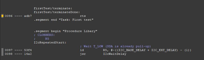
  • There appears to be an issue where there are bits being written to the register.

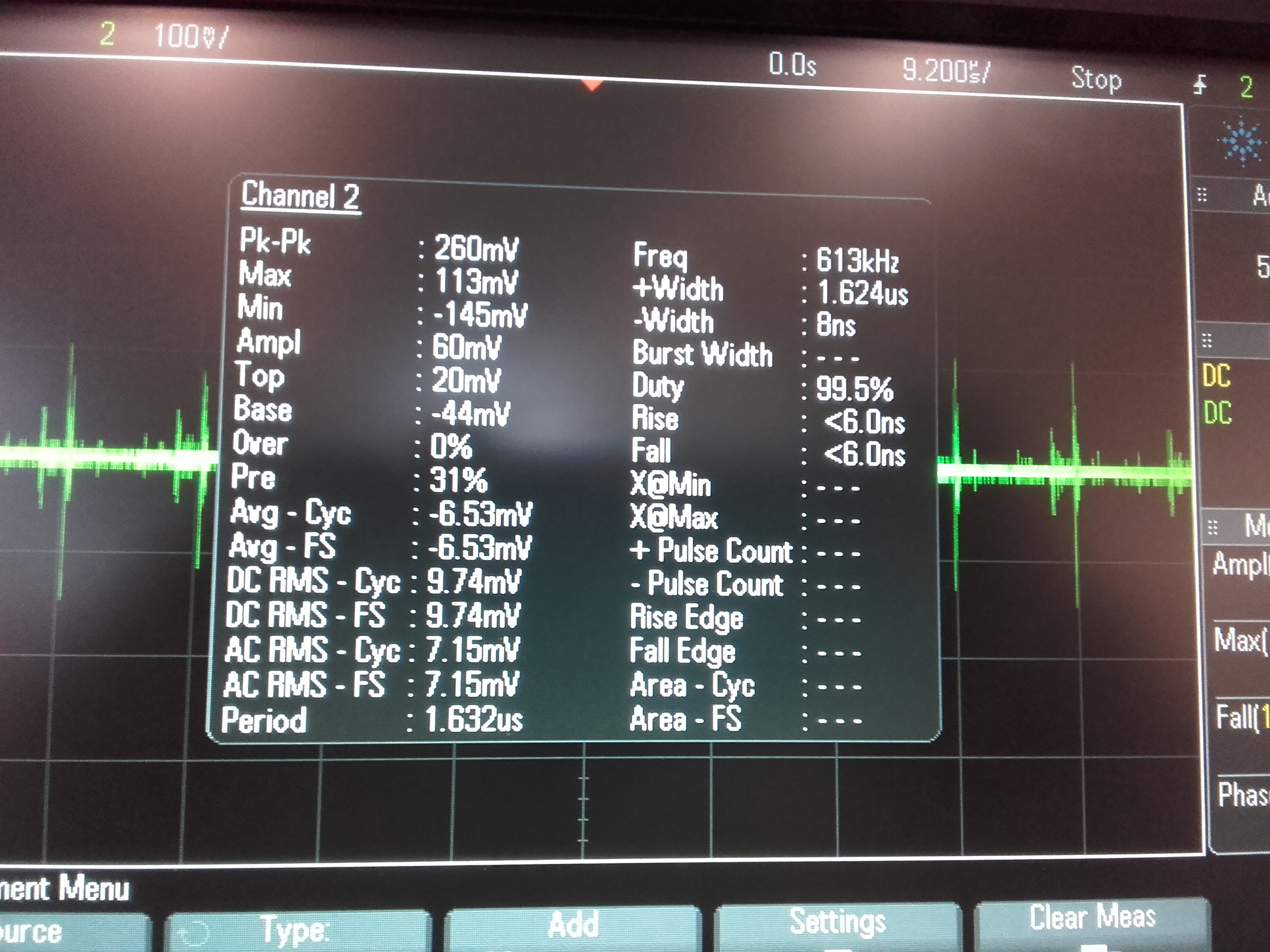
  • I've just noticed that the output from the clock pin on the oscilloscope is in the mV (~250mV p-p output) although the signal looks periodic its not square waves. I've tried multiple pins with the a different programs on sensor controller studio with no luck. Any idea what this issue could be. Is it a hardware malfunction or an Issue with SCS? The pins work for analogue I/O in project zero and the voltage pins appear to be operating fully.