This thread has been locked.

If you have a related question, please click the "Ask a related question" button in the top right corner. The newly created question will be automatically linked to this question.

cc2650: Sensor Controller Studio read multible ADCs

Part Number: CC2650
Other Parts Discussed in Thread: CC2650

Hi,

I'm using the cc2650 Sensor Tag, Sensor Controller Studio 1.5.0.188 and TI-RTOS 2.21.00.06.

I'm trying to familiarize myself with the Sensor Controller environment.

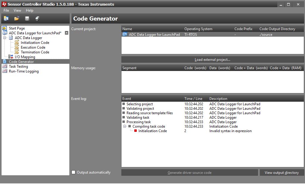
I can get the ADC Data Logger example to work but only when I use one pin and access it with a constant, when I select accessed by look-up table I get an error.

What seems to be strange is that the code doesn’t change at all. I don’t think that is supposed to be expected behavior.

Shouldn’t it be accessed in a loop with something like:

adcSelectGpioInput(cfg.pAuxioASensorOutput[n]);

It would be great if someone could post the working example code to acquire the data of several ADC Pins and buffer the output in a 2D Array.


  • If you press F1 to get the help and search/ find the ADC section you will find a code snippet for ADC sampling multiple pins.
  • Hi Roland,

    It looks like you put your execution code in the initialization code. I would suggest you take a look at the simplelink academy training "sc_02_ranger" where all steps is shown on how to properly measure an ADC signal.

    software-dl.ti.com/.../sc_02_ranger.html

    Regards,

    Klas
  • Thank you very much for your support.

    Using the Sample Code I can not use the Logging function. And I have to weak up the main function for every value I read thus rendering the use of Sensor Controll pointless.

    How can I add a additional variable?.

    Even if I just use a functioning code and change n to i, I get an error.

    It would be great if I could use another local variable so I can implement some thing like this:

    // Enable the ADC

    adcEnableSync(ADC_REF_FIXED, ADC_SAMPLE_TIME_2P7_US, ADC_TRIGGER_MANUAL);

    // Sample the sensor

    U16 n = output.head;

    for (U16 i = 0 ;i<3;i++){

    adcSelectGpioInput(cfg.pAuxioASensorOutput[i]);

    adcGenManualTrigger();

    adcReadFifo(output.pSamples[n+i]);

    }

    n=n+2;

    utilIncrAndWrap(n, BUFFER_SIZE; output.head); // BUFFER_SIZE has to be multible of 3

    // Disable the ADC

    adcDisable();

    // Schedule the next execution

    fwScheduleTask(1);

    Or may be someone can think of a way to implement this funktionality with just one variable

  • FYI: I found a working solution:

    for (U16 n = 0 ;n<INPUTS;n++){

    adcSelectGpioInput(cfg.pAuxioASensorOutput[n]);

    adcGenManualTrigger();

    n=n+output.head;

    adcReadFifo(output.pSamples[n]);

    n=n-output.head;

    }

    utilIncrAndWrap(output.head+2, BUFFER_SIZE; output.head);// BUFFER_SIZE has to be a multible of INPUTS (output.head+2=output.head+INPUTS-1)

    // Disable the ADC

    adcDisable();

    // Schedule the next execution

    fwScheduleTask(1);

  • Thanks for sharing the solution Roland.

    Regards,

    Klas