Other Parts Discussed in Thread: BLE-STACK, , CC2650
Hello everyone,
I have developed a PCB, currently at version 3 of the circuit board using CC26xx (2650 and 2640, trying out 2640R2 right now) series MCU's with BLE-stack. But I have encountered an issue in hardware with my latest circuit which I haven't noticed before in earlier versions of my PCB and I am having troubles finding the cause.
So first of, let's describe the system:
- For my graduation project, I made a PCB for a company which allowed their custom UART-protocol to be communicated through BLE. This is the basic principle simply put. It's meant to be a system made for service engineers in order to diagnose their products through their UART-protocol with a Bluetooth application.
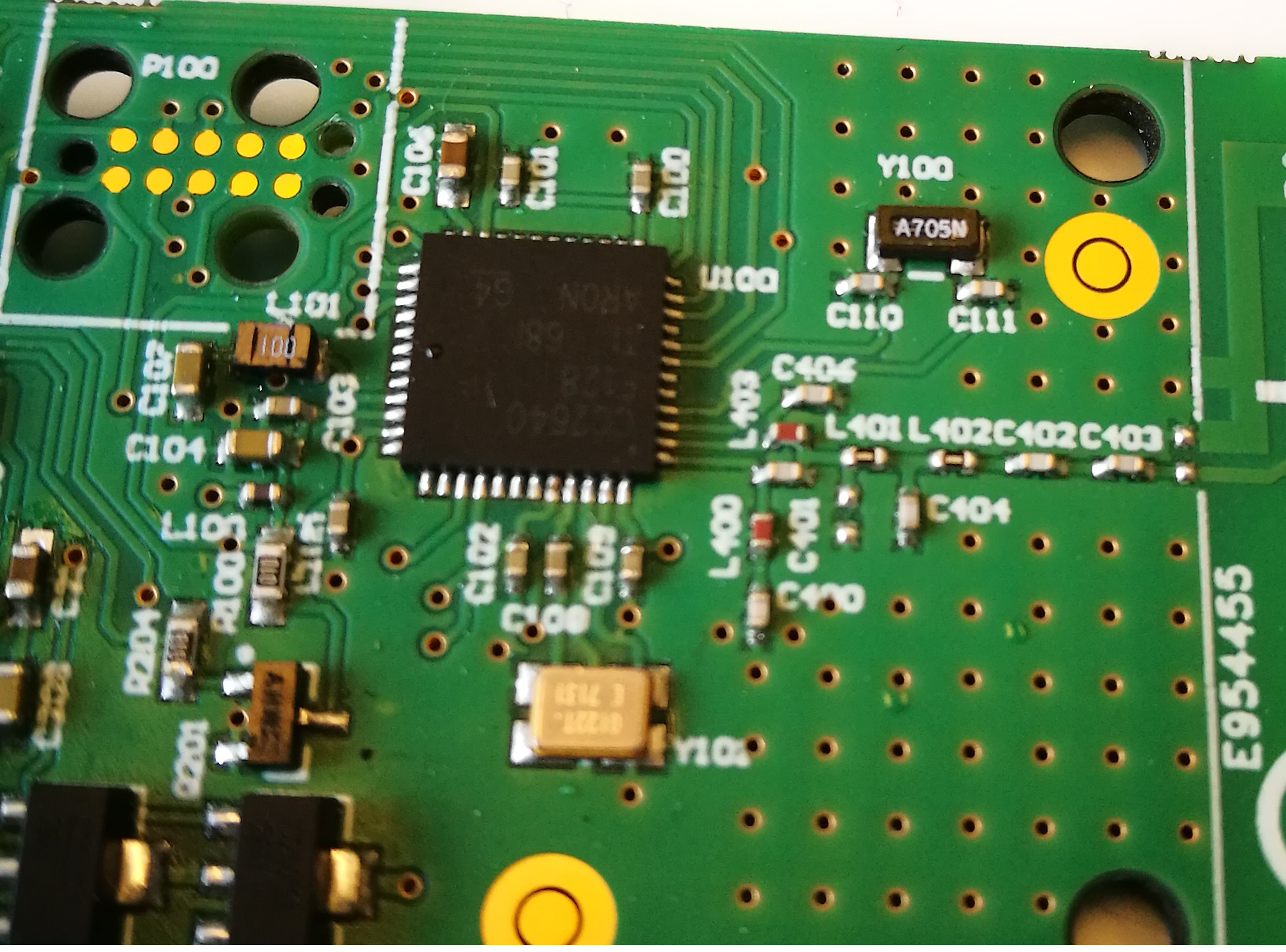
- The latest PCB consists of DC-converters (one LDO, one voltage shunt and one boost-converter), RX/TX - buffer gates, LEDs, TAG-connect for programming, PCB IFA-antenna, 24Mhz and 32kHz crystals, a Microchip LiPo charging circuit and some other basic capacitors and resistors to make everything work.
- The software running on the system is a modified Project_Zero project using services I generated with Bluetooth Developer Studio. The UART-task is placed in a seperate RTOS task and with messages through the message queue, the generated task with Bluetooth Developer Studio is notified.
Now the problem:
- I have made 10 PCB's using CC2650 and CC2640 MCU's and soldered them using solder paste and placed them in the oven once I was done placing the SMD components.
- Out of these 10 PCB's, only one seems to be running BLE-stack smoothly. When I connect to it using a Samsung Galaxy Tab A 10.1 2016, and turn on the notification where all the UART-messages are sent to, I notice a significant amount of package loss. This protocol has not changed, and always worked fine.
- Additionally, when using other devices to test (iOS and other android devices as well), one seems to suffer data loss, and the other doesnt. But in older versions of my PCB, all devices do not suffer any package losses at the aforementioned notification UUID.
- The amount of dropped packages from the notification UUID differs per PCB, where out of 10, one seems to have perfect performance.
Solutions I tried and things I noticed during testing:
- Replacing MCU, did not change anything.
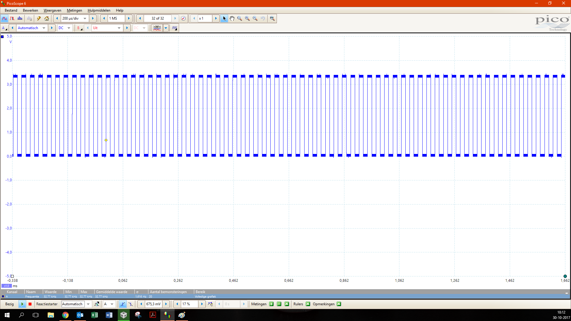
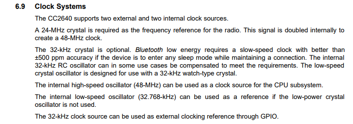
- During replacing I did notice one thing. When the PCB is still hot, the Bluetooth service functions perfectly until it cools down again. I thought this might have something to do with oscillators as these might differ in performance when temperature changes. I replaced the crystals (32kHz and 24MHz) and nothing was solved.
- During debugging, the Bluetooth worked perfectly fine.
- All other tasks in the RTOS are not affected (uart is still communicating as it should). Only Bluetooth seems to be affected.
- I removed all power components, so it is also not caused by the switching frequency of the boost-converter.
- Powering from a Launchpad without debugging does not solve the problem.
- Adding extra solder to all SMD components of the antenna did not solve the problem.
- Pressing the MCU while communicating with tablet did not affect communication, so it's not caused by connection of the pads.
I have tried countless things and I cannot seem to find the cause of this problem in this latest PCB as nothing on the side of the MCU and antenna has changed in layout. Before I have to get my hands on a Spectrum analyzer, I wanted to try asking in this forum, perhaps someone can help me with this problem?
A very simple solution would also be: using a different device than the Samsung Galaxy tab 10.1, but I want to find the cause of this problem first...
I will add schematics and layouts if this is necessary.
Thanks in advance,
Chun-Pong Tang