Part Number: CC2650
Other Parts Discussed in Thread: CC2650, CC2650MODA, CC2650STK
Tool/software: Code Composer Studio
I am trying to interface Arduino with CC2650 MODA.
For that I have refred Application Report - SWRA534A atached below
With this changes, It is working fine for CC2650 Sensortag and I am able to get data on mobile app.
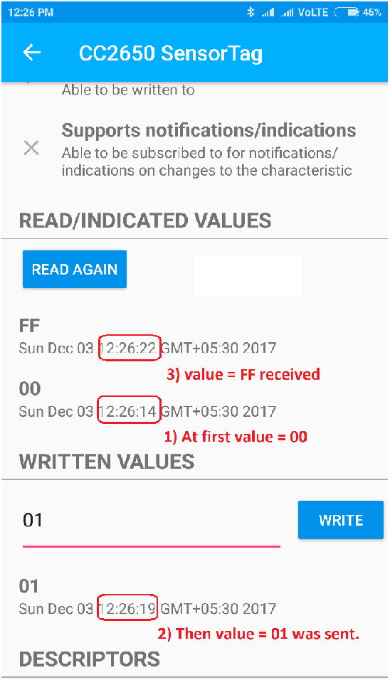
But when I upload same code on CC2650MODA, I amd not getting data on Mobile app. I am getting only Key events on mobile app.
Please find attached screenshoot for same.

Can anyone please guide me, what is problem here ?
Following are updated Board files.
/*
 * Copyright (c) 2015-2016, Texas Instruments Incorporated
 * All rights reserved.
 *
 * Redistribution and use in source and binary forms, with or without
 * modification, are permitted provided that the following conditions
 * are met:
 *
 * *  Redistributions of source code must retain the above copyright
 *    notice, this list of conditions and the following disclaimer.
 *
 * *  Redistributions in binary form must reproduce the above copyright
 *    notice, this list of conditions and the following disclaimer in the
 *    documentation and/or other materials provided with the distribution.
 *
 * *  Neither the name of Texas Instruments Incorporated nor the names of
 *    its contributors may be used to endorse or promote products derived
 *    from this software without specific prior written permission.
 *
 * THIS SOFTWARE IS PROVIDED BY THE COPYRIGHT HOLDERS AND CONTRIBUTORS "AS IS"
 * AND ANY EXPRESS OR IMPLIED WARRANTIES, INCLUDING, BUT NOT LIMITED TO,
 * THE IMPLIED WARRANTIES OF MERCHANTABILITY AND FITNESS FOR A PARTICULAR
 * PURPOSE ARE DISCLAIMED. IN NO EVENT SHALL THE COPYRIGHT OWNER OR
 * CONTRIBUTORS BE LIABLE FOR ANY DIRECT, INDIRECT, INCIDENTAL, SPECIAL,
 * EXEMPLARY, OR CONSEQUENTIAL DAMAGES (INCLUDING, BUT NOT LIMITED TO,
 * PROCUREMENT OF SUBSTITUTE GOODS OR SERVICES; LOSS OF USE, DATA, OR PROFITS;
 * OR BUSINESS INTERRUPTION) HOWEVER CAUSED AND ON ANY THEORY OF LIABILITY,
 * WHETHER IN CONTRACT, STRICT LIABILITY, OR TORT (INCLUDING NEGLIGENCE OR
 * OTHERWISE) ARISING IN ANY WAY OUT OF THE USE OF THIS SOFTWARE,
 * EVEN IF ADVISED OF THE POSSIBILITY OF SUCH DAMAGE.
 */

/*
 *  ====================== CC2650STK.c =========================================
 *  This file is responsible for setting up the board specific items for the
 *  CC2650 SensorTag.
 */


/*
 *  ====================== Includes ============================================
 */
#include <xdc/std.h>
#include <xdc/runtime/System.h>

#include <ti/sysbios/family/arm/m3/Hwi.h>
#include <ti/drivers/PIN.h>
#include <ti/drivers/pin/PINCC26XX.h>
#include <ti/drivers/Power.h>
#include <ti/drivers/power/PowerCC26XX.h>

#include <inc/hw_memmap.h>
#include <inc/hw_ints.h>
#include <driverlib/ioc.h>
#include <driverlib/udma.h>

#include "Board.h"

/*
 *  ========================= IO driver initialization =========================
 *  From main, PIN_init(BoardGpioInitTable) should be called to setup safe
 *  settings for this board.
 *  When a pin is allocated and then de-allocated, it will revert to the state
 *  configured in this table.
*/

/* Place into subsections to allow the TI linker to remove items properly */
#if defined(__TI_COMPILER_VERSION__)
#pragma DATA_SECTION(BoardGpioInitTable, ".const:BoardGpioInitTable")
#pragma DATA_SECTION(PINCC26XX_hwAttrs, ".const:PINCC26XX_hwAttrs")
#endif

const PIN_Config BoardGpioInitTable[] = {

  /*  Board_STK_LED1   | PIN_GPIO_OUTPUT_EN | PIN_GPIO_LOW | PIN_PUSHPULL | PIN_DRVSTR_MAX,
    Board_STK_LED2   | PIN_GPIO_OUTPUT_EN | PIN_GPIO_LOW | PIN_PUSHPULL | PIN_DRVSTR_MAX,
    Board_KEY_LEFT   | PIN_INPUT_EN | PIN_PULLUP | PIN_IRQ_BOTHEDGES | PIN_HYSTERESIS,
    Board_KEY_RIGHT  | PIN_INPUT_EN | PIN_PULLUP | PIN_IRQ_BOTHEDGES | PIN_HYSTERESIS,
    Board_RELAY      | PIN_INPUT_EN | PIN_PULLDOWN | PIN_IRQ_BOTHEDGES | PIN_HYSTERESIS,
    Board_MPU_INT    | PIN_INPUT_EN | PIN_PULLDOWN | PIN_IRQ_NEGEDGE | PIN_HYSTERESIS,
    Board_TMP_RDY    | PIN_INPUT_EN | PIN_PULLUP | PIN_HYSTERESIS,
    Board_BUZZER     | PIN_GPIO_OUTPUT_EN | PIN_GPIO_LOW | PIN_PUSHPULL | PIN_DRVSTR_MAX,
    Board_MPU_POWER  | PIN_GPIO_OUTPUT_EN | PIN_GPIO_HIGH | PIN_PUSHPULL | PIN_DRVSTR_MAX,
    Board_MIC_POWER  | PIN_GPIO_OUTPUT_EN | PIN_GPIO_LOW | PIN_PUSHPULL | PIN_DRVSTR_MIN,
    Board_SPI_FLASH_CS | PIN_GPIO_OUTPUT_EN | PIN_GPIO_HIGH | PIN_PUSHPULL | PIN_DRVSTR_MIN,
    Board_SPI_DEVPK_CS | PIN_GPIO_OUTPUT_EN | PIN_GPIO_LOW | PIN_PUSHPULL | PIN_DRVSTR_MIN,
    Board_AUDIO_DI | PIN_INPUT_EN | PIN_PULLDOWN,
    Board_AUDIODO | PIN_GPIO_OUTPUT_EN | PIN_GPIO_HIGH | PIN_PUSHPULL | PIN_DRVSTR_MIN,
    Board_AUDIO_CLK | PIN_INPUT_EN | PIN_PULLDOWN,
    Board_DP2 | PIN_INPUT_EN | PIN_PULLDOWN,
    Board_DP1 | PIN_INPUT_EN | PIN_PULLDOWN,
    Board_DP0 | PIN_INPUT_EN | PIN_PULLDOWN,
    Board_DP3 | PIN_INPUT_EN | PIN_PULLDOWN,
    Board_UART_RX | PIN_INPUT_EN | PIN_PULLDOWN,
    Board_UART_TX | PIN_GPIO_OUTPUT_EN | PIN_GPIO_HIGH | PIN_PUSHPULL,
    Board_DEVPK_ID | PIN_INPUT_EN | PIN_NOPULL,
    Board_SPI0_MOSI | PIN_INPUT_EN | PIN_PULLDOWN,
    Board_SPI0_MISO | PIN_INPUT_EN | PIN_PULLDOWN,
    Board_SPI0_CLK | PIN_INPUT_EN | PIN_PULLDOWN,
*/


Board_SPI0_MOSI | PIN_INPUT_EN | PIN_PULLDOWN, /*
SPI master out - slave in */
Board_SPI0_MISO | PIN_INPUT_EN | PIN_PULLDOWN, /*
SPI master in - slave out */
Board_SPI0_CLK | PIN_INPUT_EN | PIN_PULLDOWN, /*
SPI clock */
PIN_TERMINATE
};

const PINCC26XX_HWAttrs PINCC26XX_hwAttrs = {
    .intPriority = ~0,
    .swiPriority = 0
};
/*============================================================================*/

/*
 *  ============================= Power begin ==================================
 */
const PowerCC26XX_Config PowerCC26XX_config = {
    .policyInitFxn      = NULL,
    .policyFxn          = &PowerCC26XX_standbyPolicy,
    .calibrateFxn       = &PowerCC26XX_calibrate,
    .enablePolicy       = TRUE,
    .calibrateRCOSC_LF  = TRUE,
    .calibrateRCOSC_HF  = TRUE,
};
/*
 *  ============================= Power end ===================================
 */

/*
 *  ============================= UART begin ===================================
 */
#if defined(__TI_COMPILER_VERSION__)
#pragma DATA_SECTION(UART_config, ".const:UART_config")
#pragma DATA_SECTION(uartCC26XXHWAttrs, ".const:uartCC26XXHWAttrs")
#endif

/* Include drivers */
#include <ti/drivers/UART.h>
#include <ti/drivers/uart/UARTCC26XX.h>

/* UART objects */
UARTCC26XX_Object uartCC26XXObjects[CC2650STK_UARTCOUNT];

/* UART hardware parameter structure, also used to assign UART pins */
const UARTCC26XX_HWAttrsV1 uartCC26XXHWAttrs[CC2650STK_UARTCOUNT] = {
    {
        .baseAddr       = UART0_BASE,
        .powerMngrId    = PowerCC26XX_PERIPH_UART0,
        .intNum         = INT_UART0_COMB,
        .intPriority    = ~0,
        .swiPriority    = 0,
        .txPin          = Board_UART_TX,
        .rxPin          = Board_UART_RX,
        .ctsPin         = PIN_UNASSIGNED,
        .rtsPin         = PIN_UNASSIGNED
    }
};

/* UART configuration structure */
const UART_Config UART_config[] = {
    {
        .fxnTablePtr = &UARTCC26XX_fxnTable,
        .object      = &uartCC26XXObjects[0],
        .hwAttrs     = &uartCC26XXHWAttrs[0]
    },
    {NULL, NULL, NULL}
};
/*
 *  ============================= UART end =====================================
 */

/*
 *  ============================= UDMA begin ===================================
 */
/* Place into subsections to allow the TI linker to remove items properly */
#if defined(__TI_COMPILER_VERSION__)
#pragma DATA_SECTION(UDMACC26XX_config, ".const:UDMACC26XX_config")
#pragma DATA_SECTION(udmaHWAttrs, ".const:udmaHWAttrs")
#endif

/* Include drivers */
#include <ti/drivers/dma/UDMACC26XX.h>

/* UDMA objects */
UDMACC26XX_Object udmaObjects[CC2650STK_UDMACOUNT];

/* UDMA configuration structure */
const UDMACC26XX_HWAttrs udmaHWAttrs[CC2650STK_UDMACOUNT] = {
    {
        .baseAddr    = UDMA0_BASE,
        .powerMngrId = PowerCC26XX_PERIPH_UDMA,
        .intNum      = INT_DMA_ERR,
        .intPriority = ~0
    }
};

/* UDMA configuration structure */
const UDMACC26XX_Config UDMACC26XX_config[] = {
    {
         .object  = &udmaObjects[0],
         .hwAttrs = &udmaHWAttrs[0]
    },
    {NULL, NULL}
};
/*
 *  ============================= UDMA end =====================================
 */

/*
 *  ========================== SPI DMA begin ===================================
 */
/* Place into subsections to allow the TI linker to remove items properly */
#if defined(__TI_COMPILER_VERSION__)
#pragma DATA_SECTION(SPI_config, ".const:SPI_config")
#pragma DATA_SECTION(spiCC26XXDMAHWAttrs, ".const:spiCC26XXDMAHWAttrs")
#endif

/* Include drivers */
#include <ti/drivers/spi/SPICC26XXDMA.h>

/* SPI objects */
SPICC26XXDMA_Object spiCC26XXDMAObjects[CC2650STK_SPICOUNT];

/* SPI configuration structure, describing which pins are to be used */
const SPICC26XXDMA_HWAttrsV1 spiCC26XXDMAHWAttrs[CC2650STK_SPICOUNT] = {
    {
        .baseAddr           = SSI0_BASE,
        .intNum             = INT_SSI0_COMB,
        .intPriority        = ~0,
        .swiPriority        = 0,
        .powerMngrId        = PowerCC26XX_PERIPH_SSI0,
        .defaultTxBufValue  = 0,
        .rxChannelBitMask   = 1<<UDMA_CHAN_SSI0_RX,
        .txChannelBitMask   = 1<<UDMA_CHAN_SSI0_TX,
        .mosiPin            = Board_SPI0_MOSI,
        .misoPin            = Board_SPI0_MISO,
        .clkPin             = Board_SPI0_CLK,
        .csnPin             = Board_SPI0_CSN
    },
    {
        .baseAddr           = SSI1_BASE,
        .intNum             = INT_SSI1_COMB,
        .intPriority        = ~0,
        .swiPriority        = 0,
        .powerMngrId        = PowerCC26XX_PERIPH_SSI1,
        .defaultTxBufValue  = 0,
        .rxChannelBitMask   = 1<<UDMA_CHAN_SSI1_RX,
        .txChannelBitMask   = 1<<UDMA_CHAN_SSI1_TX,
        .mosiPin            = Board_SPI1_MOSI,
        .misoPin            = Board_SPI1_MISO,
        .clkPin             = Board_SPI1_CLK,
        .csnPin             = Board_SPI1_CSN
    }
};

/* SPI configuration structure */
const SPI_Config SPI_config[] = {
    {
         .fxnTablePtr = &SPICC26XXDMA_fxnTable,
         .object      = &spiCC26XXDMAObjects[0],
         .hwAttrs     = &spiCC26XXDMAHWAttrs[0]
    },
    {
         .fxnTablePtr = &SPICC26XXDMA_fxnTable,
         .object      = &spiCC26XXDMAObjects[1],
         .hwAttrs     = &spiCC26XXDMAHWAttrs[1]
    },
    {NULL, NULL, NULL}
};
/*
 *  ========================== SPI DMA end =====================================
*/


/*
 *  ============================= I2C Begin=====================================
*/
/* Place into subsections to allow the TI linker to remove items properly */
#if defined(__TI_COMPILER_VERSION__)
#pragma DATA_SECTION(I2C_config, ".const:I2C_config")
#pragma DATA_SECTION(i2cCC26xxHWAttrs, ".const:i2cCC26xxHWAttrs")
#endif

/* Include drivers */
#include <ti/drivers/i2c/I2CCC26XX.h>

/* I2C objects */
I2CCC26XX_Object i2cCC26xxObjects[CC2650STK_I2CCOUNT];

/* I2C configuration structure, describing which pins are to be used */
const I2CCC26XX_HWAttrsV1 i2cCC26xxHWAttrs[CC2650STK_I2CCOUNT] = {
    {
        .baseAddr = I2C0_BASE,
        .powerMngrId = PowerCC26XX_PERIPH_I2C0,
        .intNum = INT_I2C_IRQ,
        .intPriority = ~0,
        .swiPriority = 0,
        .sdaPin = Board_I2C0_SDA0,
        .sclPin = Board_I2C0_SCL0,
    }
};

const I2C_Config I2C_config[] = {
    {
        .fxnTablePtr = &I2CCC26XX_fxnTable,
        .object = &i2cCC26xxObjects[0],
        .hwAttrs = &i2cCC26xxHWAttrs[0]
    },
    {NULL, NULL, NULL}
};
/*
 *  ========================== I2C end =========================================
 */

/*
 *  ========================== Crypto begin ====================================
 *  NOTE: The Crypto implementation should be considered experimental
 *        and not validated!
 */
/* Place into subsections to allow the TI linker to remove items properly */
#if defined(__TI_COMPILER_VERSION__)
#pragma DATA_SECTION(CryptoCC26XX_config, ".const:CryptoCC26XX_config")
#pragma DATA_SECTION(cryptoCC26XXHWAttrs, ".const:cryptoCC26XXHWAttrs")
#endif

/* Include drivers */
#include <ti/drivers/crypto/CryptoCC26XX.h>

/* Crypto objects */
CryptoCC26XX_Object cryptoCC26XXObjects[CC2650STK_CRYPTOCOUNT];

/* Crypto configuration structure, describing which pins are to be used */
const CryptoCC26XX_HWAttrs cryptoCC26XXHWAttrs[CC2650STK_CRYPTOCOUNT] = {
    {
        .baseAddr       = CRYPTO_BASE,
        .powerMngrId    = PowerCC26XX_PERIPH_CRYPTO,
        .intNum         = INT_CRYPTO_RESULT_AVAIL_IRQ,
        .intPriority    = ~0,
    }
};

/* Crypto configuration structure */
const CryptoCC26XX_Config CryptoCC26XX_config[] = {
    {
         .object  = &cryptoCC26XXObjects[0],
         .hwAttrs = &cryptoCC26XXHWAttrs[0]
    },
    {NULL, NULL}
};
/*
 *  ========================== Crypto end ======================================
 */

/*
 *  ============================= PDM begin ====================================
*/
/* Place into subsections to allow the TI linker to remove items properly */
#if defined(__TI_COMPILER_VERSION__)
#pragma DATA_SECTION(PDMCC26XX_config, ".const:PDMCC26XX_config")
#pragma DATA_SECTION(pdmCC26XXHWAttrs, ".const:pdmCC26XXHWAttrs")
#pragma DATA_SECTION(PDMCC26XX_I2S_config, ".const:PDMCC26XX_I2S_config")
#endif

/* Include drivers */
#include <ti/drivers/pdm/PDMCC26XX.h>
#include <ti/drivers/pdm/PDMCC26XX_util.h>

/* PDM objects, one for PDM driver, one for PDM/I2S helper file */
PDMCC26XX_Object pdmCC26XXObjects[CC2650STK_PDMCOUNT];
PDMCC26XX_I2S_Object pdmCC26XXI2SObjects[CC2650STK_PDMCOUNT];

/* PDM driver hardware attributes */
const PDMCC26XX_HWAttrs pdmCC26XXHWAttrs[CC2650STK_PDMCOUNT] = {
    {
        .micPower = Board_MIC_POWER,
        .taskPriority = 2
    }
};

/* PDM configuration structure */
const PDMCC26XX_Config PDMCC26XX_config[] = {
    {
        .object = &pdmCC26XXObjects[0],
        .hwAttrs = &pdmCC26XXHWAttrs[0]
    }
};

/* PDM_I2S hardware attributes */
const PDMCC26XX_I2S_HWAttrs pdmC26XXI2SHWAttrs[CC2650STK_PDMCOUNT] = {
    {
        .baseAddr       = I2S0_BASE,
        .intNum         = INT_I2S_IRQ,
        .powerMngrId    = PowerCC26XX_PERIPH_I2S,
        .intPriority    = ~0,
        .mclkPin        = PIN_UNASSIGNED,
        .bclkPin        = Board_AUDIO_CLK,
        .wclkPin        = PIN_UNASSIGNED,
        .ad0Pin         = Board_AUDIO_DI,
    }
};

/* PDM_I2S configuration structure */
const PDMCC26XX_I2S_Config PDMCC26XX_I2S_config[] = {
    {
        .object  = &pdmCC26XXI2SObjects[0],
        .hwAttrs = &pdmC26XXI2SHWAttrs[0]
    },
    { NULL, NULL }
};

/*
 *  ============================= PDM end ======================================
 */

/*
 *  ========================= RF driver begin ==================================
 */
/* Include drivers */
#include <ti/drivers/rf/RF.h>

/* RF hwi and swi priority */
const RFCC26XX_HWAttrs RFCC26XX_hwAttrs = {
    .hwiCpe0Priority = ~0,
    .hwiHwPriority   = ~0,
    .swiCpe0Priority =  5,
    .swiHwPriority   =  5,
};

/*
 *  ========================== RF driver end ===================================
 */

/*
 *  ========================= Display begin ====================================
 */
/* Place into subsections to allow the TI linker to remove items properly */
#if defined(__TI_COMPILER_VERSION__)
#pragma DATA_SECTION(Display_config, ".const:Display_config")
#pragma DATA_SECTION(displaySharpHWattrs, ".const:displaySharpHWattrs")
#pragma DATA_SECTION(displayUartHWAttrs, ".const:displayUartHWAttrs")
#endif

#include <ti/mw/display/Display.h>
#include <ti/mw/display/DisplaySharp.h>
#include <ti/mw/display/DisplayUart.h>

/* Structures for UartPlain Blocking */
DisplayUart_Object        displayUartObject;

#ifndef BOARD_DISPLAY_UART_STRBUF_SIZE
#define BOARD_DISPLAY_UART_STRBUF_SIZE    128
#endif
static char uartStringBuf[BOARD_DISPLAY_UART_STRBUF_SIZE];

const DisplayUart_HWAttrs displayUartHWAttrs = {
    .uartIdx      = Board_UART,
    .baudRate     =     115200,
    .mutexTimeout = BIOS_WAIT_FOREVER,
    .strBuf = uartStringBuf,
    .strBufLen = BOARD_DISPLAY_UART_STRBUF_SIZE,
};

/* Structures for SHARP */
DisplaySharp_Object displaySharpObject;

#ifndef BOARD_DISPLAY_SHARP_SIZE
#define BOARD_DISPLAY_SHARP_SIZE    96 // 96->96x96 is the most common board, alternative is 128->128x128.
#endif
static uint8_t sharpDisplayBuf[BOARD_DISPLAY_SHARP_SIZE * BOARD_DISPLAY_SHARP_SIZE / 8];

const DisplaySharp_HWAttrs displaySharpHWattrs = {
    .spiIndex    = Board_SPI0,
    .csPin       = Board_LCD_CS,
    .extcominPin = Board_LCD_EXTCOMIN,
    .powerPin    = Board_LCD_POWER,
    .enablePin   = Board_LCD_ENABLE,
    .pixelWidth  = BOARD_DISPLAY_SHARP_SIZE,
    .pixelHeight = BOARD_DISPLAY_SHARP_SIZE,
    .displayBuf  = sharpDisplayBuf,
};

/* As the pins for UART and Watch Devpack conflict, prefer UART by default */
#if !defined(BOARD_DISPLAY_EXCLUDE_UART) && !defined(BOARD_DISPLAY_EXCLUDE_LCD)
#  define BOARD_DISPLAY_EXCLUDE_LCD
#endif

/* Array of displays */
const Display_Config Display_config[] = {
#if !defined(BOARD_DISPLAY_EXCLUDE_UART)
    {
        .fxnTablePtr = &DisplayUart_fxnTable,
        .object      = &displayUartObject,
        .hwAttrs     = &displayUartHWAttrs,
    },
#endif
#if !defined(BOARD_DISPLAY_EXCLUDE_LCD)
    {
        .fxnTablePtr = &DisplaySharp_fxnTable,
        .object      = &displaySharpObject,
        .hwAttrs     = &displaySharpHWattrs
    },
#endif
    { NULL, NULL, NULL } // Terminator
};

/*
 *  ========================= Display end ======================================
 */