This thread has been locked.

If you have a related question, please click the "Ask a related question" button in the top right corner. The newly created question will be automatically linked to this question.

CC2564MODAEM: Controller is not starting after releasing nSHUTD

Part Number: CC2564MODAEM
Other Parts Discussed in Thread: CC2564, SN74AVC4T245, SN74LVC2T45

Hey, 

i'm using the CC2564MODAEM connected to a STM32L476RGT over UART. My problem is that the CC2564  starts not every time when i plug the power in.

After a power up like in this article (http://processors.wiki.ti.com/index.php/CC256x_Testing_Guide) the CC2564 will not start everytime.

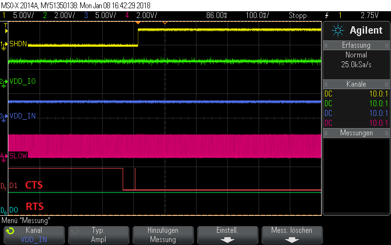
In case it's not working, the behaiver is exactly like the picture "Figure: Proper Power Up Sequence " excapt that the HCI_RTS is not pulled down from the CC2564 and absolutely no output on the TX_DGB.

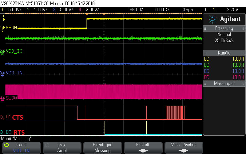
In case the everything is working i get the output from the TX_DGB pin and i can connect over bluetooth.

On the software side, i'm using this example "http://processors.wiki.ti.com/index.php/CC256x_TI_Bluetooth_Stack_SPPDemo_App

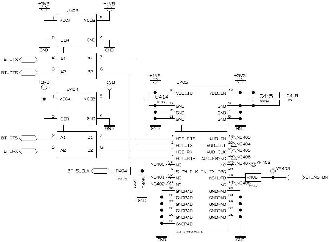
My connection:

Thaks for your help.
  • Hi Michael,

    My apologies for the late reply on this. From the schematic, it looks like you are going thru a level shifter on the HCI bus correct? What is the PN of the level shifter. Our recommended part to use here is the SN74AVC4T245. Since you are communicating via HCI there may be an issue if the correct level shifter is not being used and see intermittent boot up as you are seeing.

    Thanks,
    Riz
  • Hi Riz,

    thanks for your answer.

    The partnumber is TI SN74LVC2T45.


    I'm not sure if the problem is the level shifter because i checked the power supply and the power levels.
    Is it right, that during the startup phase the bluetooth controler should start and give us some information at the debug pin? Without that the main controller sends anything over uart to the bluetooth controller?

    Something like this (in this case it worked):

    There are the pictures of the oscilloscope (sometimes measured in front and after the level shifter):

                            It works                                                                                                                               Not working

    Thank you!

    Michael

  • Michael,

    Since the scope capture of the not working case shows that the RTS line is not being asserted low, this indicates that the device is not powered-up correctly. Please make sure that all the requirements mentioned in the "Power Supply Sequencing" section of the device datasheet are met. 

    There is also a rise-time requirement for the nSHUTD pin (20 us maximum) as indicated in the datasheet. I see that you have a resistor in the path of the nSHUTD signal. This might be causing this reliability issue. Please make sure that all the other pins also comply with the datasheet recommendations covered in the "Reference Design Schematics" section.

    Best regards,

    Vihang

  • Thanks for your answer,

    i found the problem, it was the "slow clock" from the µc.

    The clock looked good but had sometimes gaps in the signal. (Fix it by increasing the  capability on the µc side)


    Thanks to all.

    Michael