Tool/software: Code Composer Studio
1、Summary of the problem
The CC2640R2 launchpad is shown in picture 1 , which is the one I use. Now the bootloader function is needed in CC2640R2, the UART TXD should be DIO6 and the UART RXD should be DIO7 , which is the requirement of our company project. Besides this , the bootloader backdoor enable controller should be DIO23.

picture 1
However , the bootloader function cannot work properly after the default IO port is changed . Where am I wrong ?
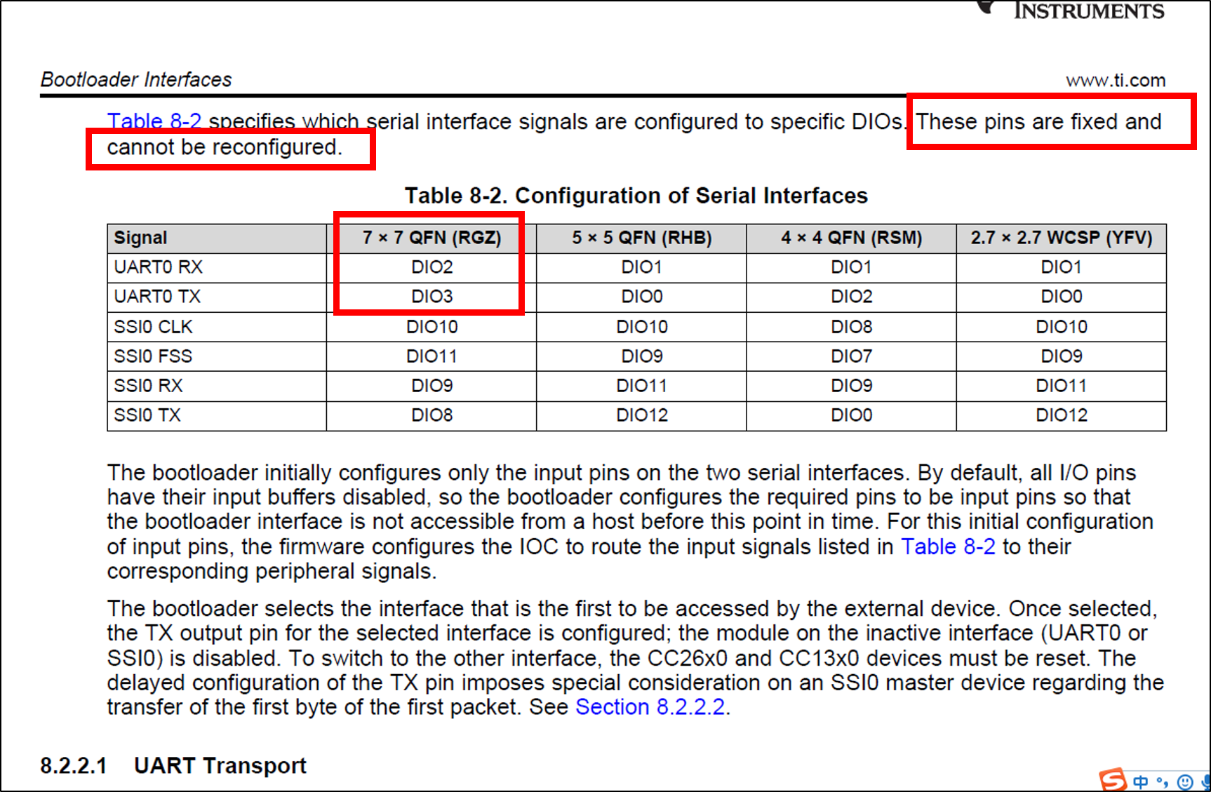
Two experiments were conducted in CC2640R2. The first experiment uses DIO6 、DIO7 and DIO23 to realize the bootloader function . The second experiment uses the default IO port to realize the bootloader function ,which keeps DIO2 as UART RXD、DIO3 as UART TXD、DIO14 as the bootloader backdoor enable controller .
The bootloader function can work correctly in the first experiment , however , it cannot work properly in the second experiment . Picture 2 shows the result and the IO pin configuration .

picture 2
2、My detail steps of the first experiment
(1) Use the simple_peripheral project in SDK. Firstly , use DIO7 as UART RXD、DIO6 as UART TXD in CC2640R2_LAUNCHXL.h , as picture 3 shows. Then delete the CC2640R2_LAUNCHXL_PIN_RLED and CC2640R2_LAUNCHXL_PIN_GLED, as shown in picture 4.

picture 3

picture 4
(2) Delete GPIOCC26XX_DIO_07 and GPIOCC26XX_DIO_06 in CC2640R2_LAUNCHXL.c , as picture 5 shows.

picture 5
(3) Change the configuration of bootloader backdoor enable controller. Configure SET_CCFG_BL_CONFIG_BL_PIN_NUMBER as DIO23 in ccfg.c , as picture 6 shows .

picture 6
(4) Delete the defined parameters related to DIO23 in CC2640R2_LAUNCHXL.h , as picture 7 and picture 8 shows.

picture 7

picture 8
(5) Delete the defined parameters related to DIO23 in CC2640R2_LAUNCHXL.c , as picture 9 and picture 10 shows.
picture 9
picture 10
(6) Connect DIO6 and DIO7 of the CC2640R2 launchpad with my computer through USB-TTL, as shown in picture 11 . Disconnect the jumper of TXD and RXD in CC2640R2 LAUNCHPAD , as shown in picture 12.

picture 11

picture 12
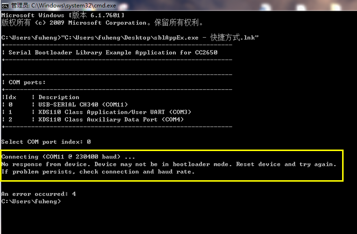
(7) Rebuild the simple_peripheral project and flash it into CC2640R2 LAUNCHPAD . Press the reset button in CC2640R2 LAUNCHPAD while DIO23 in the low level . Then pull up the DIO23 after reset completed . At last , flashing the bin file into CC2640R2 LAUNCHPAD through sblAppEx.exe . However , the CMD window shows CC2640R2 LAUNCHPAD is not in bootloader mode , as picture 13 shows . Where am I wrong ?
picture 13
3、The documents related to bootloader
(1)reference manual
www.ti.com/.../swra466a.pdf
(2)sblAppEx.exe can be downloaded here
www.ti.com/.../getliterature.tsp
4、Attachments
(1) the location of simple_peripheral in my computer
C:\ti\simplelink_cc2640r2_sdk_1_40_00_45\examples\rtos\CC2640R2_LAUNCHXL\blestack\simple_peripheral
(2) hex2bin app can be downloaded here
sourceforge.net/.../
(3) simplelink_cc2640r2_sdk_1_40_00_45 can be downloaded here
dev.ti.com/.../
(4) CC2640R2 launchpad can be bought here
www.ti.com/.../launchxl-cc2640r2
(5) my source code can be downloaded here (including: CC2640R2_LAUNCHXL.h 、 CC2640R2_LAUNCHXL.c 、 ccfg.c)
5、My developing environment
CCS:Code Composer Studio 7.2.0
SDK:simplelink_cc2640r2_sdk_1_40_00_45
hardware:CC26640R2 launchpad develop kit
system:win7 64 bit