This thread has been locked.

If you have a related question, please click the "Ask a related question" button in the top right corner. The newly created question will be automatically linked to this question.

CC2640: I2C Fast Mode

Part Number: CC2640
Other Parts Discussed in Thread: CC1350STK

I have I2C bus working on a CC2640 at 100khz, but only barely, since the rise time on the clock/data pulses is about 0.9 usec (spec says should be <1 usec).

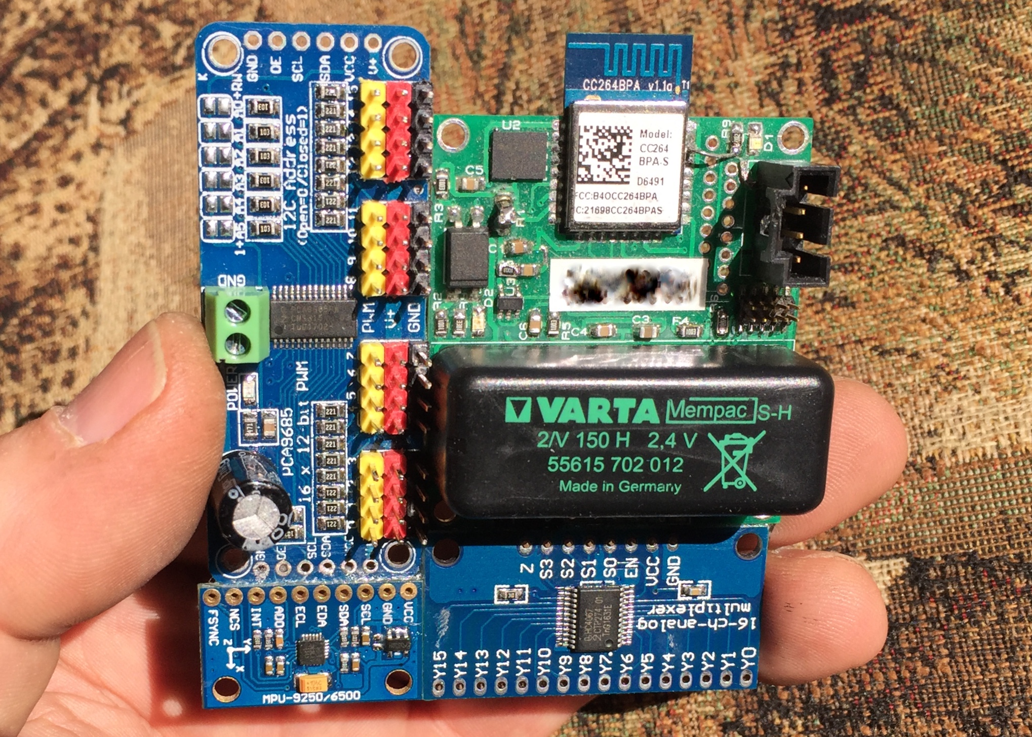
I have two external I2C daughterboards (MP9250 IMU chip and PCA9685 PWM chip) on the SDA/SCL lines of my CC2640.

The only pullups in use are the internal ones of the CC2640.

I am unable to use 400khz fast mode due to the fact that the rise time of 0.9 usec is just too far from the spec max of 0.3 usec.

Fall times are good for both modes ~60 nsec.

If I look at SCL from the CC2640 without any attachment to other devices, the rise time is still 0.5 usec 

My CC2640 is itself on a CC264BPA-S daughterboard and I am only running it at 2.8v.

This is my SDA/SCL pin assignment:

#define Board_I2C0_SCL0      IOID_12 
#define Board_I2C0_SDA0      IOID_0 

What can I do to fix this?

Thanks,

Dale

  • Hi,

    Can you give the link to where you found the spec? Are you using the I2C from the sensor controller as described in this guide:
    www.ti.com/.../swru537.pdf

    Best wishes
  • I used code from i2ctmp007_CC1350STK_TI example project to implement i2c into my project.

    I believe this link shows specs taken from the Phillips standard: community.cypress.com/.../DOC-12635

    I will review your link for clues.

    Sorry I edited my rise/fall times a few times, I was getting some affects from my logic analyser leads and my scope leads, but I believe they are pretty close to actual now. I am also seeing a difference between clock and data rise times.
  • I seem to have solved the Fast mode rise/fall time problem by adding '| PIN_DRVSTR_MAX' to both SDA and SCL pin assignment lines in the library file I2CCC26XX.c

    Rise/fall times are now about 95 nsec.

    I do have another issue with the CC2640 not being able to pull the SDA and SCL lines down to the common ground of all boards.

    As you can see in this scope image capture, only the slave device gets the SDA down to ground when it sends an ACK (but the CC2640 seems to hold SDA low between the 1st and 2nd ACK during its transmission of 0x00, strange):

    Any ideas on this, as I said, the CC2640 runs on 2.8v while the other boards on the I2C bus run on 3.3v.

    FYI here is a pic of my circuit board 'assembly' before I wired the I/O and power pins:

  • Can't figure out why, since I put '| PIN_DRVSTR_MAX' in  I2CCC26XX.c and with the only pullups on my SDA/SCL lines being the ones put in place by the CC2640, the CC2640 can't pull the lines down to logic low levels consistently.  Using '| PIN_DRVSTR_MAX' fixed rise/fall times but caused another issue.

    CC2640 only pulls the lines down to just over 1v, and my PWM and MPU boards on the I2C bus don't see this as LOW.  When these boards ACK back on SDA, they can pull the SDA line to ~0v.

    I have a feeling that the answer is somewhere in this chart:

    What is the difference between 'current mode' and 'drive strength'?  Datasheet, TRM and Google does not answer that?

    Would switching my SDA/SCL lines to Extended Current Mode pins help (not so easy to do but if I have to, I will, but first, advice on what chance this has of helping would be nice)?

    How do I make sure the I2C library is setting slew rate to 'normal'?

    Why am I having to fool around in a Library to make this work?

  • I ran the original  I2CCC26XX.c library file to get back to square 1 before I try other things.

    Lo and behold, no more rise/fall time issues or any low logic level issues on my SDA/SCL lines.

    Now I am completely baffled but I need to get on with things.

    So, I guess there is no answer to be found here as I do not really know what resolved my issue.

    Sorry for wasting your time, I will come back here if it magically re-appears.

    Here is a read of the magnetometer calibration values at 400kHz: