This thread has been locked.

If you have a related question, please click the "Ask a related question" button in the top right corner. The newly created question will be automatically linked to this question.

CC2640R2F-Q1: PCB Antenna design (Small Size 2.4 GHz PCB antenna),

Part Number: CC2640R2F-Q1
Other Parts Discussed in Thread: CC2640R2F

Hi,

Our customer is designing CC2640R2F based application with PCB antenna.
We are referring to the Small Size 2.4 GHz PCB antenna layout design application note SWRA117D.

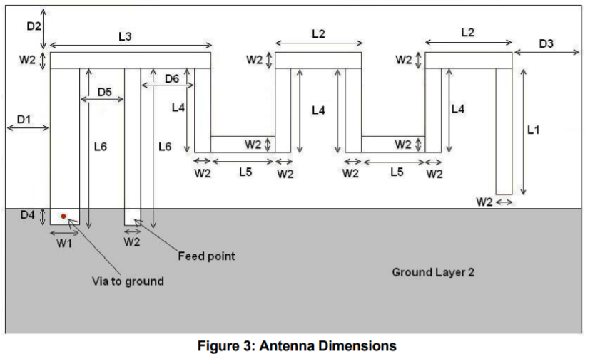
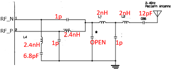
Please let us know if below Filter circuit(values) will be OK for the recommended layout.

Best Regards
paddu

  • Hi Paddu,

    The components shown in the figure above do not include antenna matching. I would recommend adding a pi-network between the 12 pF cap and the antenna (as close to the antenna as possible). Leave the shunts to ground unpopulated for now and use a 0-ohm resistor for the series component.

    Cheers,
    Fredrik
  • Hi Fredrik,

    Thank you for the information.

    I am sorry, as I am new to this,
    could you please let me if there is any reference on pi-network,
    what values of Capacitor and inductors is recommended.

    But, the application circuit mentioned in the datasheet don't have the pi-network.

    Best Regards
    paddu
  • Hi Paddu,

    The pi network values can only be found by measuring the antenna impedance in your actual product. You can find more information here: www.ti.com/.../swra161

    The application circuit in the datasheet is simplified and assumes a 50 ohm antenna.

    Cheers,
    Fredrik