This thread has been locked.

If you have a related question, please click the "Ask a related question" button in the top right corner. The newly created question will be automatically linked to this question.

CC2640R2F: Correct RF connection for DSBGA part

Part Number: CC2640R2F
Other Parts Discussed in Thread: CC2650,

Hello,

We are using the DSBGA CC2640R2F on our board; according to the driver library, this has a different RF output stage, compared to the CC2650 for instance:

#elif defined( CC2650EM_4XS )

#define RF_FE_MODE_AND_BIAS ( RF_FE_SINGLE_ENDED_RFP | \
RF_FE_EXT_BIAS )

#elif defined( CC2640R2EM_CXS )

#define RF_FE_MODE_AND_BIAS ( RF_FE_SINGLE_ENDED_RFN | \
RF_FE_EXT_BIAS )

This implies the single-ended antenna connection should be connected to RF_N instead of RF_P...?

Could you provide a circuit fragment equivalent to this, but for the CC2640R2F DSBGA package please?

Many thanks,

Richard

  • Hi Richard,

    You are free to use RF_N instead, but from a layout point-of-view RF_P is better. You may even go with differential configuration, but then you are on your own as this has not been characterized for the WCSP package.

    For layout details/recommendations, refer to the reference design: www.ti.com/.../swrc336

    Cheers,
    Fredrik
  • Hi Fredrik,

    Thanks for the super-fast response!

    Should I then change the provided code in ble_user_config.h to:

    #elif defined( CC2640R2EM_CXS )

    #define RF_FE_MODE_AND_BIAS ( RF_FE_SINGLE_ENDED_RFP | \
    RF_FE_EXT_BIAS )

    (i.e. replace RFP with RFN)?

    Many thanks,
    Richard
  • Hi Richard,

    Yes, I would recommend using RF-N and following the reference design I linked to.

    Cheers,
    Fredrik
  • Many thanks, that's very useful.

    The actual reason I came across this is that in doing pre-EMC compliance testing, using the Rx test mode HCI_EXT_ModemTestRxCmd(0), we are seeing a first harmonic spike at around 4816MHz.  Have you seen this on any other layouts or can you provide any pointers that might cause this?


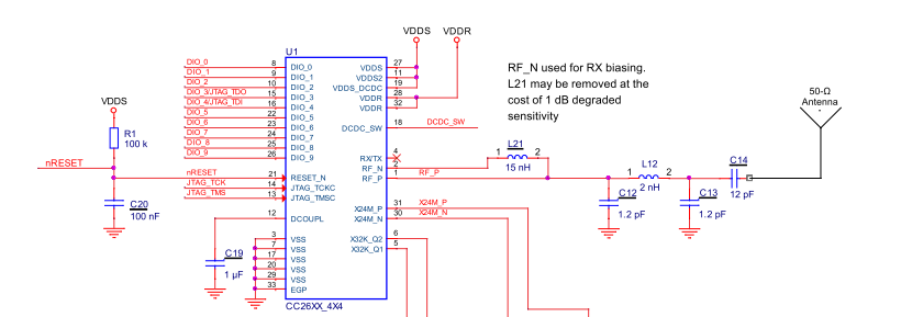
    Our schematic fragment is:

    Our layout is extremely tightly packed next to the micro so there are no long traces.  I'm not asking for a layout review (yet :)) but any pointers you may have regarding the harmonic would be appreciated.

    Many thanks,

    Richard

  • Hi Richard,

    We have seen that the RX spur is higher on the WCSP reference design than for the QFN packages. Still, the reference design has good margin to the EU requirement.

    Btw. you only state that you see a spur, but does it actually violate any requirements?

    TYpically the RX spurs leak out through the RF pin. If the second harmonic filtering is poor, which could be due to poor layout, the level can increase.

    Cheers,
    Fredrik