


Tool/software: Code Composer Studio
According to the TI official guide 《Cc2640_Adding_a_UART_or_SPI_driver_to_a_Sample_Project》,it shows how to add NPI_SPI into simple_peripheral project . However , the code in
《Cc2640_Adding_a_UART_or_SPI_driver_to_a_Sample_Project》is SPI SLAVE only ,instead of SPI MASTER. How to configure the code offered in the TI official guide so that it can be used as SPI
MASTER ?
How to build the communication between two CC2640 LAUNCHPADs through NPI_SPI ?
My detail steps are as followed:
1.Using two CC2640 LAUNCHPADs , act as SPI MASTER and SPI SLAVE respectively .Code running on two CC2640 LAUNCHPADs is simple_peripheral project .
2.On the first CC2640 LAUNCHPAD , add NPI_SPI into simple_peripheral project according to 《Cc2640_Adding_a_UART_or_SPI_driver_to_a_Sample_Project》.
(1) download the “tl.h” and “tl.c ” file . The path is shown in attachments 6(7) and 6(8).
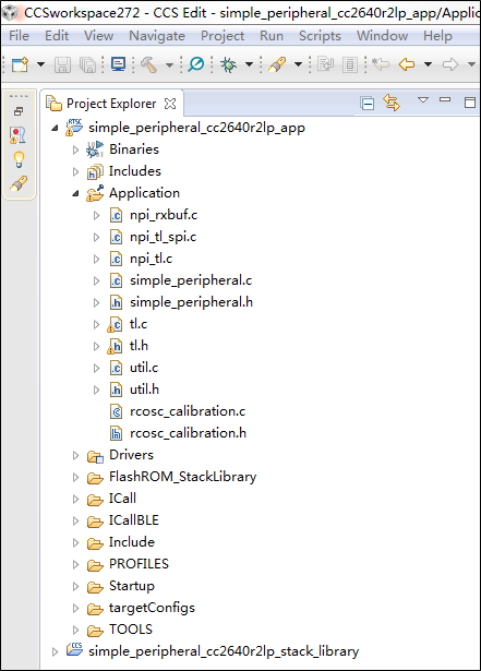
(2) add NPI_SPI into simple_peripheral project according to 《Cc2640_Adding_a_UART_or_SPI_driver_to_a_Sample_Project》.After completed , the result is shown in picture 1.
(3) according to the TI official guide 《NPI》, there has MRDY and SRDY wires . Add predefined symbols "NPI_FLOW_CTRL" in simple_peripheral project , as shown in picture 2.

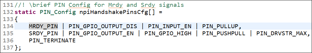
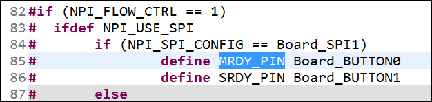
(4) In npi_tl.c , MRDY_PIN and SRDY_PIN is defined , as shown in picture 3. MRDY_PIN and SRDY_PIN is Board_BUTTON0 and Board_BUTTON1 respectively , as shown in picture 4 .
(5) In NPITLSPI_initializeTransport() function of npi_tl_spi.c , spiParams.mode is SPI_SLAVE . The code is shown as followed:
void NPITLSPI_initializeTransport(Char *tRxBuf, Char *tTxBuf, npiCB_t npiCBack)
{
    SPI_Params spiParams;

    TransportRxBuf = tRxBuf;
    TransportTxBuf = tTxBuf;
    npiTransmitCB = npiCBack;

    // Initialize the SPI driver
    Board_initSPI();

    // Configure SPI parameters
    SPI_Params_init(&spiParams);

    // Slave mode
    spiParams.mode = SPI_SLAVE;
    spiParams.bitRate = SPI_SLAVE_BAUD_RATE;
    spiParams.frameFormat = SPI_POL1_PHA1;
    spiParams.transferMode = SPI_MODE_CALLBACK;
    spiParams.transferCallbackFxn = NPITLSPI_CallBack;

    // Attempt to open SPI
    spiHandle = SPI_open(NPI_SPI_CONFIG, &spiParams);
    return;
}
(6) running the code when configuration completed on the first CC2640 LAUNCHPAD .
3.On the second CC2640 LAUNCHPAD , configuring the code to make it serve as SPI MASTER.
(1) configure the spiParams.mode as SPI_MASTER in npi_tl_spi.c .The code is shown as followed:
void NPITLSPI_initializeTransport(Char *tRxBuf, Char *tTxBuf, npiCB_t npiCBack)
{
    SPI_Params spiParams;

    TransportRxBuf = tRxBuf;
    TransportTxBuf = tTxBuf;
    npiTransmitCB = npiCBack;

    // Initialize the SPI driver
    Board_initSPI();

    // Configure SPI parameters
    SPI_Params_init(&spiParams);

    // Slave mode
    spiParams.mode = SPI_MASTER;
    spiParams.bitRate = SPI_SLAVE_BAUD_RATE;
    spiParams.frameFormat = SPI_POL1_PHA1;
    spiParams.transferMode = SPI_MODE_CALLBACK;
    spiParams.transferCallbackFxn = NPITLSPI_CallBack;

    // Attempt to open SPI
    spiHandle = SPI_open(NPI_SPI_CONFIG, &spiParams);
    return;
}
(2) In the SimpleBLEPeripheral_TLpacketParser() function of simple_peripheral.c , TLwrite() funtion is executed after TLread() function , the code is shown as followed. However , the code
can not be used as SPI MASTER . How the configure the SimpleBLEPeripheral_TLpacketParser() function , so that the code can serve as SPI MASTER ?
#if defined (NPI_USE_UART) || defined (NPI_USE_SPI)
static void SimpleBLEPeripheral_TLpacketParser(void)
{
  //read available bytes
  uint8_t len = TLgetRxBufLen();
  if (len >= APP_TL_BUFF_SIZE)
  {
    len = APP_TL_BUFF_SIZE;
  }
  TLread(appRxBuf, len);

  // ADD PACKET PARSER HERE
  // for now we just echo...

  TLwrite(appRxBuf, len);
}
#endif //TL
4.Connecting two CC2640 LAUNCHPADs , as shown in picture 5 . Running the code on two CC2640 LAUNCHPADs respectively , but the SPI communication failed . Where am I wrong ?

5.“npi_tl_uart_m.c” file is located in simplelink_cc2640r2_sdk_1_40_00_45 , which is used for NPI UART MASTER . Is there any similar files which used for NPI SPI MASTER ?
6.Attachments
(1) my source code of NPI SPI SLAVE which running on the first CC2640 LAUNCHPAD can be downloaded here :
(2) my source code of NPI MASTER SLAVE which running on the second CC2640 LAUNCHPAD can be downloaded here :
(3) TI official guide 《Cc2640_Adding_a_UART_or_SPI_driver_to_a_Sample_Project》 can de downloaded here :
(4) TI official guide 《NPI》 can de downloaded here :
(5) the location of simple_peripheral project in my computer is shown as followed:
C:\ti\simplelink_cc2640r2_sdk_1_40_00_45\examples\rtos\CC2640R2_LAUNCHXL\blestack\simple_peripheral
(6) simplelink_cc2640r2_sdk_1_40_00_45 can de downloaded here :
(7) CC2640R2 launchpad can be bought here :
(8) “tl.h” can de downloaded here :
(9) “tl.c” can de downloaded here :

