Other Parts Discussed in Thread: CC2640R2F
Tool/software: Code Composer Studio
HI,
i am unable to get the data from the IR sensor led (0x0d) and RED led (0x0c). i want to read the data from that registers .
and i am not getting the interrupt pin in the board then which code i will write to make any pin to interrupt pin.
my code is :-
*/
#include <stdint.h>
#include <stddef.h>
#include <unistd.h>
/* Driver Header files */
#include <ti/drivers/GPIO.h>
#include <ti/drivers/I2C.h>
#include <ti/display/Display.h>
/* Example/Board Header files */
#include "Board.h"
#define I2C_WRITE_ADDR 0xAE
#define I2C_READ_ADDR 0xAF
//register addresses
#define REG_INTR_STATUS_1 0x00
#define REG_INTR_STATUS_2 0x01
#define REG_INTR_ENABLE_1 0x02
#define REG_INTR_ENABLE_2 0x03
#define REG_FIFO_WR_PTR 0x04
#define REG_OVF_COUNTER 0x05
#define REG_FIFO_RD_PTR 0x06
#define REG_FIFO_DATA 0x07
#define REG_FIFO_CONFIG 0x08
#define REG_MODE_CONFIG 0x09
#define REG_SPO2_CONFIG 0x0A
#define REG_LED1_PA 0x0C
#define REG_LED2_PA 0x0D
#define REG_PILOT_PA 0x10
#define REG_MULTI_LED_CTRL1 0x11
#define REG_MULTI_LED_CTRL2 0x12
#define REG_TEMP_INTR 0x1F
#define REG_TEMP_FRAC 0x20
#define REG_TEMP_CONFIG 0x21
#define REG_PROX_INT_THRESH 0x30
#define REG_REV_ID 0xFE
#define REG_PART_ID 0xFF
#define true 1
#define false 0
#define FS 25 //sampling frequency
#define BUFFER_SIZE (FS* 4)
#define MA4_SIZE 4 // DONOT CHANGE
#define min(x,y) ((x) < (y) ? (x) : (y))
//uch_spo2_table is approximated as -45.060*ratioAverage* ratioAverage + 30.354 *ratioAverage + 94.845 ;
const uint8_t uch_spo2_table[184]={ 95, 95, 95, 96, 96, 96, 97, 97, 97, 97, 97, 98, 98, 98, 98, 98, 99, 99, 99, 99,
99, 99, 99, 99, 100, 100, 100, 100, 100, 100, 100, 100, 100, 100, 100, 100, 100, 100, 100, 100,
100, 100, 100, 100, 99, 99, 99, 99, 99, 99, 99, 99, 98, 98, 98, 98, 98, 98, 97, 97,
97, 97, 96, 96, 96, 96, 95, 95, 95, 94, 94, 94, 93, 93, 93, 92, 92, 92, 91, 91,
90, 90, 89, 89, 89, 88, 88, 87, 87, 86, 86, 85, 85, 84, 84, 83, 82, 82, 81, 81,
80, 80, 79, 78, 78, 77, 76, 76, 75, 74, 74, 73, 72, 72, 71, 70, 69, 69, 68, 67,
66, 66, 65, 64, 63, 62, 62, 61, 60, 59, 58, 57, 56, 56, 55, 54, 53, 52, 51, 50,
49, 48, 47, 46, 45, 44, 43, 42, 41, 40, 39, 38, 37, 36, 35, 34, 33, 31, 30, 29,
28, 27, 26, 25, 23, 22, 21, 20, 19, 17, 16, 15, 14, 12, 11, 10, 9, 7, 6, 5,
3, 2, 1 } ;
static Display_Handle display;
/*
* ======== mainThread ========
*/
void *mainThread(void *arg0)
{
uint8_t txBuffer[3];
uint8_t rxBuffer[2];
I2C_Handle i2c;
I2C_Params i2cParams;
I2C_Transaction i2cTransaction;
/* Call driver init functions */
Display_init();
GPIO_init();
I2C_init();
/* Open the HOST display for output */
display = Display_open(Display_Type_UART, NULL);
if (display == NULL) {
while (1);
}
/* Turn on user LED */
GPIO_write(Board_GPIO_LED0, Board_GPIO_LED_ON);
Display_printf(display, 0, 0, "Starting the i2ctmp007 example\n");
/* Create I2C for usage */
I2C_Params_init(&i2cParams);
i2cParams.bitRate = I2C_400kHz;
i2c = I2C_open(Board_I2C_TMP, &i2cParams);
if (i2c == NULL) {
Display_printf(display, 0, 0, "Error Initializing I2C\n");
while (1);
}
else {
Display_printf(display, 0, 0, "I2C Initialized!\n");
}
while(1)
{
/* INTR_ENABLE 1*/
txBuffer[0] = REG_INTR_ENABLE_1; /* 0x02 */
txBuffer[1]=0xc0; /* write data 0xc0 into interrupt enable 1 */
i2cTransaction.slaveAddress = 0x57;
i2cTransaction.writeBuf = txBuffer;
i2cTransaction.writeCount = 2;
/* INTR_ENABLE 2*/
txBuffer[0] = REG_INTR_ENABLE_2; /*0x03 */
txBuffer[1]=0x00; /* write data 0x00 into interrupt enable 2 */
i2cTransaction.slaveAddress = 0x57;
i2cTransaction.writeBuf = txBuffer;
i2cTransaction.writeCount = 2;
/* FIFO WRITE POINTER*/
txBuffer[0] = REG_FIFO_WR_PTR; /* 0x04*/
txBuffer[1]=0x00; /* write data 0x00 into fifo write pointer */
i2cTransaction.slaveAddress = 0x57;
i2cTransaction.writeBuf = txBuffer;
i2cTransaction.writeCount = 2;
/* FIFO OVERFLOW COUNTER*/
txBuffer[0] = REG_OVF_COUNTER; /* 0x05*/
txBuffer[1]=0x00; /* write data 0x00 into fifo over flow counter */
i2cTransaction.slaveAddress = 0x57;
i2cTransaction.writeBuf = txBuffer;
i2cTransaction.writeCount = 2;
/* FIFO read POINTER*/
txBuffer[0] = REG_FIFO_RD_PTR; /* 0x06*/
txBuffer[1]=0x00; /* write data 0x00 into fifo write pointer */
i2cTransaction.slaveAddress = 0x57;
i2cTransaction.writeBuf = txBuffer;
i2cTransaction.writeCount = 2;
/* FIFO CONFIGURATION*/
txBuffer[0] = REG_FIFO_CONFIG; /* 0x08*/
txBuffer[1]=0x4F; /* write data 0x00 into fifo write pointer */
i2cTransaction.slaveAddress = 0x57;
i2cTransaction.writeBuf = txBuffer;
i2cTransaction.writeCount = 2;
/* mode configuration */
txBuffer[0] = REG_MODE_CONFIG; /* mode configuration address 0x09 */
txBuffer[1]=0x03; /* Configuration of HR mode by write data 0xc2 in mode config*/
i2cTransaction.slaveAddress = 0x57;
i2cTransaction.writeBuf = txBuffer;
i2cTransaction.writeCount = 2;
/* spo2 configuration*/
txBuffer[0] = REG_SPO2_CONFIG; /* 0x0A*/
txBuffer[1]=0x27; /* write data 0x00 into SPO2 CONFIGURATION */
i2cTransaction.slaveAddress = 0x57;
i2cTransaction.writeBuf = txBuffer;
i2cTransaction.writeCount = 2;
/* PILOT MODE*/
txBuffer[0] =REG_PILOT_PA ;/*0x10*/
txBuffer[1] =0x7F ; /* WRITE 0X7F INTO PILOT */
i2cTransaction.slaveAddress = 0x57;
i2cTransaction.writeBuf = txBuffer;
i2cTransaction.writeCount = 2;
/* LED 1 enable */
txBuffer[0] = REG_LED1_PA ; /* 0x0c*/
txBuffer[1] =0x24 ; /* write 0x24 into led 1*/
i2cTransaction.slaveAddress = 0x57;
i2cTransaction.writeBuf = txBuffer;
i2cTransaction.writeCount = 2;
i2cTransaction.readBuf = rxBuffer; /* read led 1 data */
i2cTransaction.readCount =2;
if (I2C_transfer(i2c, &i2cTransaction)) {
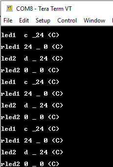
Display_printf(display, 0, 0, "led1 %x _%x (C)\n", txBuffer[0],txBuffer[1]);
Display_printf(display, 0, 0, "rled1 %x _ %x (C)\n", rxBuffer[0],rxBuffer[1]);
}
/* LED 2 enable */
txBuffer[0] =REG_LED2_PA ; /* 0x0d*/
txBuffer[1] =0x24 ; /* write 0x24 into led 2*/
i2cTransaction.slaveAddress = 0x57;
i2cTransaction.writeBuf = txBuffer;
i2cTransaction.writeCount = 2;
i2cTransaction.readBuf = rxBuffer; /* read led 2 data */
i2cTransaction.readCount =2;
if (I2C_transfer(i2c, &i2cTransaction)) {
Display_printf(display, 0, 0, "led2 %x _ %x (C)\n", txBuffer[0],txBuffer[1]);
Display_printf(display, 0, 0, "rled2 %x _ %x (C)\n", rxBuffer[0],rxBuffer[1]);
}
else {
Display_printf(display, 0, 0, "I2C Bus fault\n");
}
sleep(1);
}
/* Deinitialized I2C */
I2C_close(i2c);
Display_printf(display, 0, 0, "I2C closed!\n");
return (NULL);
}
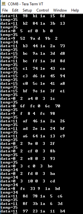
and the display output is