


Tool/software: Code Composer Studio
Hi!
I would like to ask your help on the following issue:
Using as base project: “Simple_peripheral_cc2640r2lp_oad_offchip” , I am developing on CC2640R2 Launchpad. It was working perfectly.
I had developed a custom hardware, which electronic circuit build-up differ from the Launchpad’s one, because I need to provide the CC2640R2 power supply from 1.8V externally.
For the hardware re-design, I used CC2650EM-4XS-Ext_Reg_2_0_0 as reference project.
The bim_oad_offchip_cc2640r2lp_app is part of the Simple_peripheral. But the bim_oad_offchip_cc2640r2lp_app contains a ccfg.c file, where it is possible configure the DC/DC converter.
Based on my knowledge, the simple_peripheral_cc2640r2lp_oad_offchip_app project does not has a ccfg configuration, due to the fact that the bootloader set these parameters. Am I correct ?
I had been modified the ccfg.c file in the Bim project as described in swra486a.pdf. Based on the custom hardware, I had written a custom board.h file, and I had uploaded the previously tested and working software on the custom hardware.
My ccfg.c DC/DC settings:
//#####################################
// Alternative DC/DC settings
//#####################################

#ifndef SET_CCFG_SIZE_AND_DIS_FLAGS_DIS_ALT_DCDC_SETTING
// #define SET_CCFG_SIZE_AND_DIS_FLAGS_DIS_ALT_DCDC_SETTING     0x0    // Alternative DC/DC setting enabled
#define SET_CCFG_SIZE_AND_DIS_FLAGS_DIS_ALT_DCDC_SETTING        0x1    // Alternative DC/DC setting disabled
#endif

#ifndef SET_CCFG_MODE_CONF_1_ALT_DCDC_VMIN
#define SET_CCFG_MODE_CONF_1_ALT_DCDC_VMIN              0x0        // 2.25V
#endif

#ifndef SET_CCFG_MODE_CONF_1_ALT_DCDC_DITHER_EN
#define SET_CCFG_MODE_CONF_1_ALT_DCDC_DITHER_EN         0x0        // Disable
// #define SET_CCFG_MODE_CONF_1_ALT_DCDC_DITHER_EN      0x1        // Enable
#endif

#ifndef SET_CCFG_MODE_CONF_1_ALT_DCDC_IPEAK
#define SET_CCFG_MODE_CONF_1_ALT_DCDC_IPEAK             0x2        // 39mA
#endif

//#####################################
// Power settings
//#####################################

#ifndef SET_CCFG_MODE_CONF_VDDR_TRIM_SLEEP_DELTA
#define SET_CCFG_MODE_CONF_VDDR_TRIM_SLEEP_DELTA        0xF        // Signed delta value +1 to apply to the VDDR_TRIM_SLEEP target (0xF=-1=default=no compensation)
#endif

#ifndef SET_CCFG_MODE_CONF_DCDC_RECHARGE
// #define SET_CCFG_MODE_CONF_DCDC_RECHARGE             0x0        // Use the DC/DC during recharge in powerdown
#define SET_CCFG_MODE_CONF_DCDC_RECHARGE                0x1        // Do not use the DC/DC during recharge in powerdown
#endif

#ifndef SET_CCFG_MODE_CONF_DCDC_ACTIVE
// #define SET_CCFG_MODE_CONF_DCDC_ACTIVE               0x0        // Use the DC/DC during active mode
#define SET_CCFG_MODE_CONF_DCDC_ACTIVE                  0x1        // Do not use the DC/DC during active mode
#endif

#ifndef SET_CCFG_MODE_CONF_VDDS_BOD_LEVEL
// #define SET_CCFG_MODE_CONF_VDDS_BOD_LEVEL            0x0        // VDDS BOD level is 2.0V
#define SET_CCFG_MODE_CONF_VDDS_BOD_LEVEL               0x1        // VDDS BOD level is 1.8V (or 1.65V for external regulator mode)
#endif

#ifndef SET_CCFG_MODE_CONF_VDDR_CAP
#define SET_CCFG_MODE_CONF_VDDR_CAP                     0x3A       // Unsigned 8-bit integer representing the min. decoupling capacitance on VDDR in units of 100nF
#endif

#ifndef SET_CCFG_MODE_CONF_VDDR_TRIM_SLEEP_TC
#define SET_CCFG_MODE_CONF_VDDR_TRIM_SLEEP_TC           0x1        // Temperature compensation on VDDR sleep trim disabled (default)
// #define SET_CCFG_MODE_CONF_VDDR_TRIM_SLEEP_TC        0x0        // Temperature compensation on VDDR sleep trim enabled
#endif
The software is running, and UART monitoring confirms all OK. Sensors are operating, the BLE waiting for connection in “Advertising” mode.
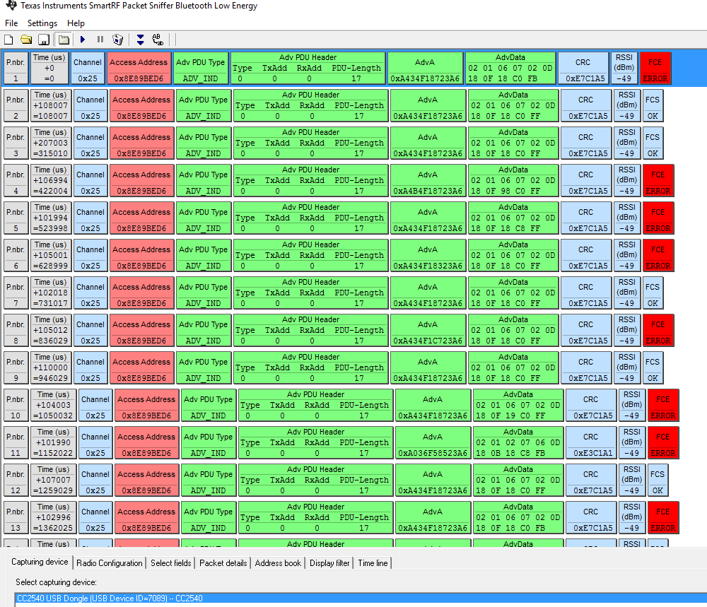
BUT ERROR: the device can be discovered by other devices, but cannot be connected, cannot retrieve the service list, cannot communicate. Device name "N/A" or "Unknown" in BLE monitor. The BLE packet sniffer list the advertising packages, but there are tons of "FCE ERROR" (50%).
I was suspect the 32Khz oscillator instability, but I had tried 3 different type of oscillator. I had also measured the oscillator signal with an oscilloscope, but it always showed perfectly stable.
After this, based on the documentation of swra499b.pdf I had switch to internal RC oscillator, but the problem still exist.

The RF front-end design identical with the Launchpad’s one. The power supply is stable 1.8V.
In my opinion the error is in correlation with the power supply build-up design, but I cannot identify what else should be modified apart form those I listed above, to ensure, that the BLE communication work perfectly.
Many thanks for your concrete help and support,
Laszlo
Simplelink CC2640R2 SDK 1.50.00.58 | CCS 7.3.0.00019


