This thread has been locked.

If you have a related question, please click the "Ask a related question" button in the top right corner. The newly created question will be automatically linked to this question.

RTOS/CC2640: I2C Bulk write: Gaps between bytes, clock loss

Part Number: CC2640
Other Parts Discussed in Thread: MSP430F5438A

Tool/software: TI-RTOS

Hy,

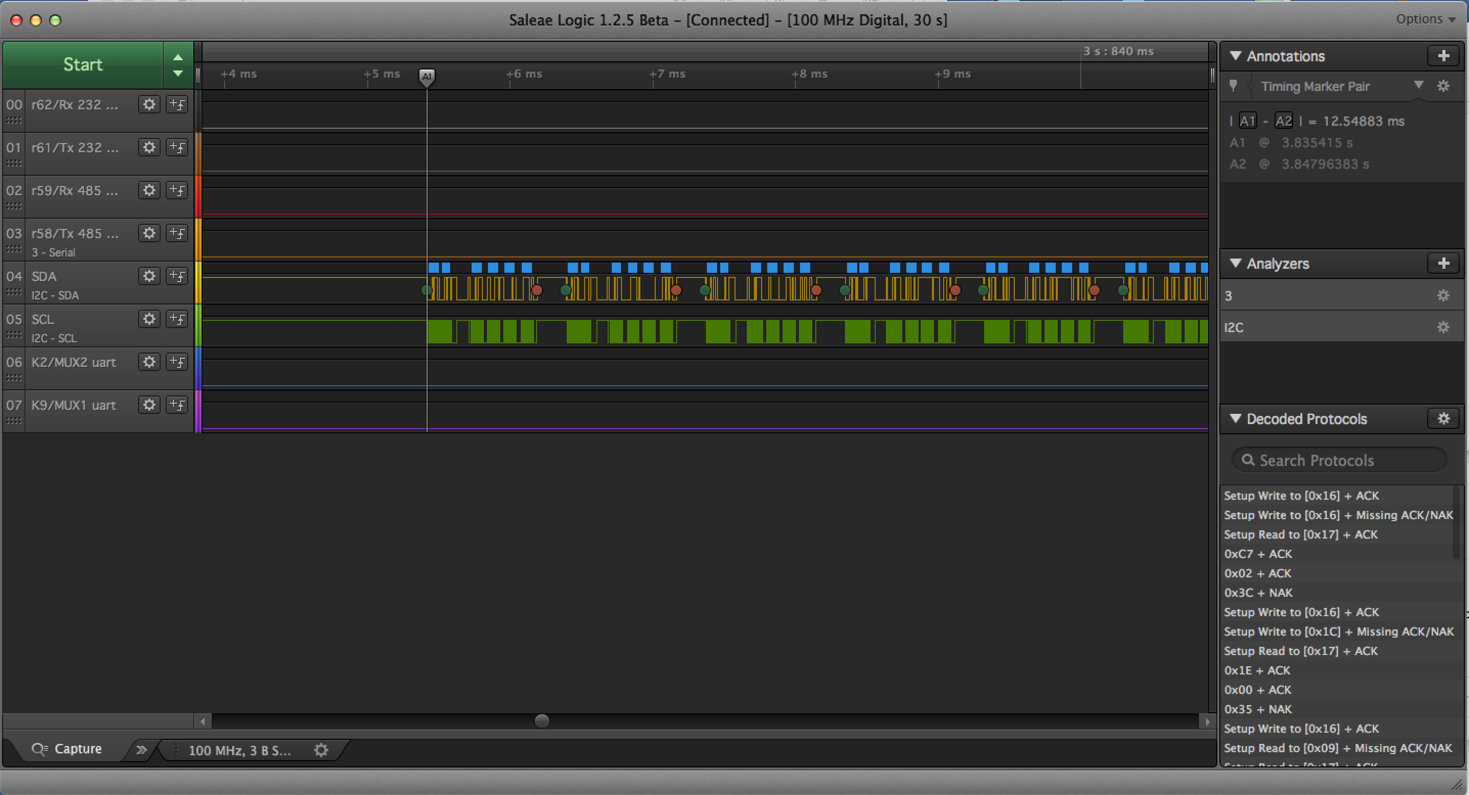
I see two strange effect when writing bulk data (258byte) to I2C:

1)

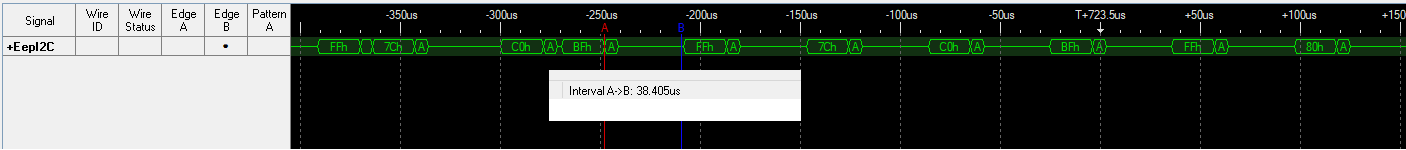
Sometimes (about 2/3 of the cases) there is a gap of 38us between two bytes

2)

After some bytes (i.e. 24), one clock cycle seems shorter then usual (only 155ns). This byte is not understood by the I2C (eeprom) and gets not acknowledged.

Afterwards, the SDA line is kept low until a new I2C command appears. This seems to happen only on one of my devices, other ones work fine

Is there a possible improvement for 1) and what could be the root cause for 2)

Regards

Harald

  • Hello Harald,
    Are you using the TI-RTOS driver?
    Which version?
  • Hy Eirik,

    yes, I use the TI-RTOS driver. I modified the existing bsp_i2c file to be able to send more than 256 byte. Then I use

    bool bspI2cWrite(uint8_t *data, uint32_t len)
    {
      I2C_Transaction masterTransaction;
    
      masterTransaction.writeCount   = len;
      masterTransaction.writeBuf     = data;
      masterTransaction.readCount    = 0;
      masterTransaction.readBuf      = NULL;
      masterTransaction.slaveAddress = slaveAddr;
    
      return I2C_transfer(i2cHandle, &masterTransaction) == TRUE;
    }

    As for the version: The I2C.c file is in folder

    ti\tirtos_simplelink_2_13_00_06\packages\ti\drivers

    Does that include the version of the driver? Or where can I find more information about the driver?

    Best regards

    Harald

  • Hello Harald,
    There has been considerable updates to the I2C Driver since tirtos_simplelink_2_13_00_06. The current version for CC2640 is tirtos_cc13xx_cc26xx_2_21_01_08. I could not find any items in the release notes that seems to be relevant. I would test a later/latest version to verify if this problem still persists.

    http://software-dl.ti.com/dsps/dsps_public_sw/sdo_sb/targetcontent/tirtos/index.html

  • Hy Eirik,

    thanks for your response

    >I would test a later/latest version to verify if this problem still persists.

    Is there a recommended way to do so? A step-by-step porting guide?

    I am a bit afraid of screwing up my development environment. I need to support several old branches of the firmware, each built with my current tool chain. Also, I may not need to update the stack portion of the firmware. I have many battery powered devices in the field and can't afford to update stack and app of all of them. Am I sure that I can go back to the original version once I have installed a newer version of tirtos? Can I try to only change the I2C driver part of the tirtos?

    Regards

    Harald

  • I have seen this exact symptom. It occurred when a higher priority Task interrupted the I2C Task, and took over the CPU, while that higher priority Task had stuff to do. I'm pretty sure I2C_Transfer() does not set up an interrupt driven transfer, but rather this runs on that process.

    In my application, I had all the heavy data-moving done over SPI (which is 100 times faster than I2C). Devices which become ready and require SPI, can send a SWI (from the HWI_Task, a.k.a., the ISR), and the SPI bus work can begin as a Task. Its only when you try to do too much (maybe more than 20 micro-seconds of work) from your ISR that you have problems.

    Also, we have no control over the 1-ms Timer interrupt that TI-RTOS runs (as the highest interrupt priority).
    Well, actually, we have some control. I found that the interrupt latency of the Timer interrupt so large that UART interrupts at 115 kb could not always be serviced. I fixed this by some careful changes in the project cfg file.
  • Hi Harald,

    Could you share how you setup the I2C driver itself, is it in callback or blocking mode?

    @ Allan

    I would not expect a high priority task to introduce this kind of behavior into the I2C driver. Higher priority Hwi could however delay the data output as this is handled from Hwi context (in short, all I2C transfers should be considered interrupt driven).

    I'm curious on where you picked up the 1-ms Timer interrupt from? Non of the CC26xx and CC13xx TI-RTOS examples as far as I know is delivered with a periodic system tick but instead uses the dynamic system tick approach (only tick when needed). Furthermore, the typical clock period is set to 10 us. I know there is other devices in the SimpleLink family that utilize 1 ms system ticks, what devices where you working on at the time?
  • Hi M-W,

    I managed to save and now find an image ... this was a four months ago in the development of an MSP430F5438A product, running on its internal 8 MHz clock.  

    In the image above, I have captured an I2C transfer, which is apparently 12.5 ms in duration (according to timing markers A1 and A2).  During this time, there was a extended SCL clock exactly every 1ms, lasting roughly 100us.   I instrumented every single one of my ISR's, (with timing signals on spare GPIO pins), and determined it wasn't my ISRs, but TI-RTOS's 1ms Timer interrupt.   I found the code for that, and saw it ran as an NMI (non-maskable interrupt) every 1ms.

    I am aware that the system tick can run at different intervals, and can be dynamic.  This is a project cfg file setting.  Yes, I could have changed that, however, that wouldn't fix my problem -- only make it less frequent.

    The I2C device was very well behaved, and I didn't lose data (I think).  In my case, the problem was the interrupt latency was so bad I lost UCSI_A2 receiver interrupts on a 115kb device.   This character flow from the other device was critical, because the protocol had no error detection or retries.

    I had to reduce the interrupt latency of the periodic system tick.  I ended up fixing the problem in two ways.  First, I fiddled with the project cfg file, and had the periodic system tick function do less.  (by turning off the code-timing option, and one other option which I don't remember the exact detail).   Second, we made a PCB fix, and installed an external crystal connected to XT2IN and XT2OUT, and now run the MSP430 with an SMCLK of 12 Mhz.

    We accomplished the reduction of interrupt latency, and the time to run the periodic system tick function was reduced to about 60 us. (or less now -- I haven't timed it in months).   I also checked the interrupt latency of all my own ISRs, and verified that they run in typically 10us to 20us.

    Sorry Harold, this is a little off-topic for you.  In your case the SCL signal is being badly mangled, in my case it was being extended.

  • Hy M-W,

    >Could you share how you setup the I2C driver itself, is it in callback or blocking mode?

    Basically, I use all standard calls from the Sensor Tag example, I2C in blocking mode:

    /* Default I2C parameters structure */
    const I2C_Params I2C_defaultParams = {
        I2C_MODE_BLOCKING,  /* transferMode */
        NULL,               /* transferCallbackFxn */
        I2C_400kHz,         /* bitRate */
        NULL                /* custom */
    };
    void I2C_init(void)
    {
        if (I2C_count == -1) {
            /* Call each driver's init function */
            for (I2C_count = 0; I2C_config[I2C_count].fxnTablePtr != NULL; I2C_count++) {
                I2C_config[I2C_count].fxnTablePtr->initFxn((I2C_Handle)&(I2C_config[I2C_count]));
            }
        }
    }
    void I2C_Params_init(I2C_Params *params)
    {
        *params = I2C_defaultParams;
    }
    I2C_Handle I2C_open(unsigned int index, I2C_Params *params)
    {
        I2C_Handle handle;
    
        /* Get handle for this driver instance */
        handle = (I2C_Handle)&(I2C_config[index]);
    
        return (handle->fxnTablePtr->openFxn(handle, params));
    }
    
    void bspI2cInit(void)
    {
      Semaphore_Params semParamsMutex;
    
      // Create protection semaphore
      Semaphore_Params_init(&semParamsMutex);
      semParamsMutex.mode = Semaphore_Mode_BINARY;
      Semaphore_construct(&mutex, 1, &semParamsMutex);
    
      // Reset the I2C controller
      HapiResetPeripheral(PRCM_PERIPH_I2C0);
    
      I2C_init();
      I2C_Params_init(&i2cParams);
      i2cParams.bitRate = I2C_400kHz;
      i2cHandle = I2C_open(Board_I2C, &i2cParams);
    
      // Initialise local variables
      slaveAddr = 0xFF;
      interface = BSP_I2C_INTERFACE_0;
    
      if (i2cHandle == NULL)
      {
        Task_exit();
      }
    }

  • Hi Allan,

    This explains the timer you where talking about. In the case of CC13xx and CC26xx however, this is not the case as the system tick per default is set to 10us/tick with dynamic settings (you only get an interrupt if the application actually needs one). I'm not that familiar with the MSP430 family at all, I will keep what you learned in mind for the future, thanks for sharing!

    To move back to your topic Harald, the delay between two bytes that you see now and then can be connected to the system doing something else. The transfer is interrupt driver but chances is that there is currently another Hwi running at this point which delays the I2C one.

    The strange clock cycle I will have to look closer at. I'll try to put together a test and see if I can reproduce it. As it only happens on one of your devices, it is very likely that it is hardware related and a problem with that particular board.