


Part Number: CC2640R2F
Hi TI,
I am measuring VDDS with the sensor controller as follows:
// ADC measurement of VDDS with referrence to internal voltage referrence
// Select VDDS as input
adcSelectIntInput(ADC_INPUT_VDDS);
// Enable the ADC
adcEnableSync(ADC_REF_FIXED, ADC_SAMPLE_TIME_2P7_US, ADC_TRIGGER_MANUAL);
// Measure and store the result
adcGenManualTrigger();
U16 Current_VDDS;
adcReadFifo(Current_VDDS);
output.VDDS = Current_VDDS;
// Disable the ADC
adcDisable();
Issue:
I try to make a tolerance calculation to see what VDDS values does the sensor controller measure at different temperatures.
I did not find any characteristic data (tolerance, temperature coefficient) about the internal 4.3-V reference voltage.
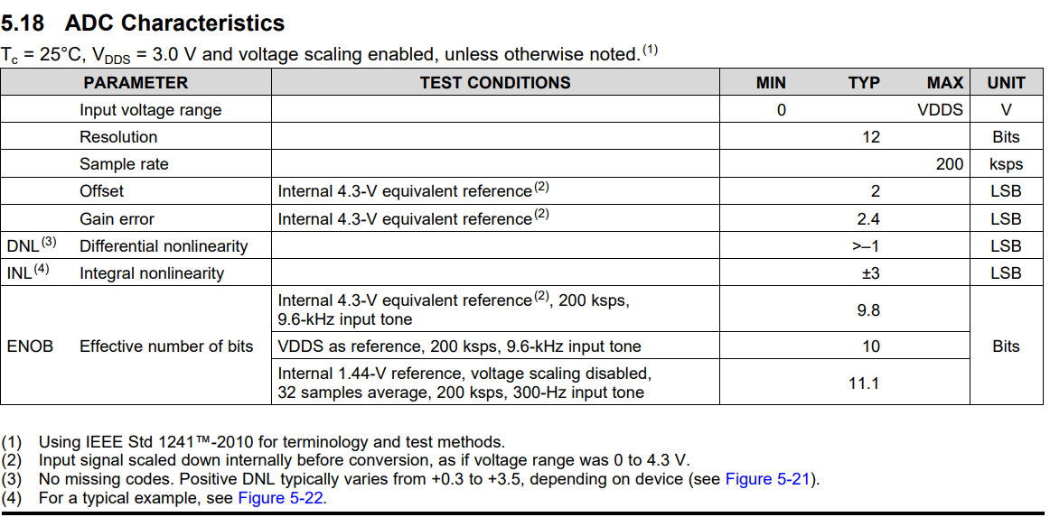
In the datasheet SWRS204A –DECEMBER 2016–REVISED JANUARY 2017 ADC Characteristics I found the following:
Equivalent fixed internal reference (input voltage scaling enabled). For best accuracy, the ADC conversion should be initiated through the TIRTOS API in order to include the gain/offset compensation factors stored in FCFG1.
My questions are:
[1] - What happens if I am working with the Sensor controller and hence not with a TIRTOS API, do I have a compensation then or I have to take in account both the Offset and Gain error?
In other words which errors / nonlinearities should I take into account?
[2] - How could I calculate the maximum and minimum measurement error for the above measurement at different temperatures (from -40 to +85 °C)?
Thank you in advance!
