


Part Number: CC2640R2F
Other Parts Discussed in Thread: CC2592, CC2650
Hi,
I am doing a CC2640R2F + CC2592 Project using CC2650 + CC2592 Reference Design. I want to know how to communicate CC2640R2F to CC2592 including setting the TXPOWER. From the Schematic Diagram of CC2650 + CC2592 Reference Design, CC2650 DIO7, DIO13, DIO14 is connected to CC2592. See, below.
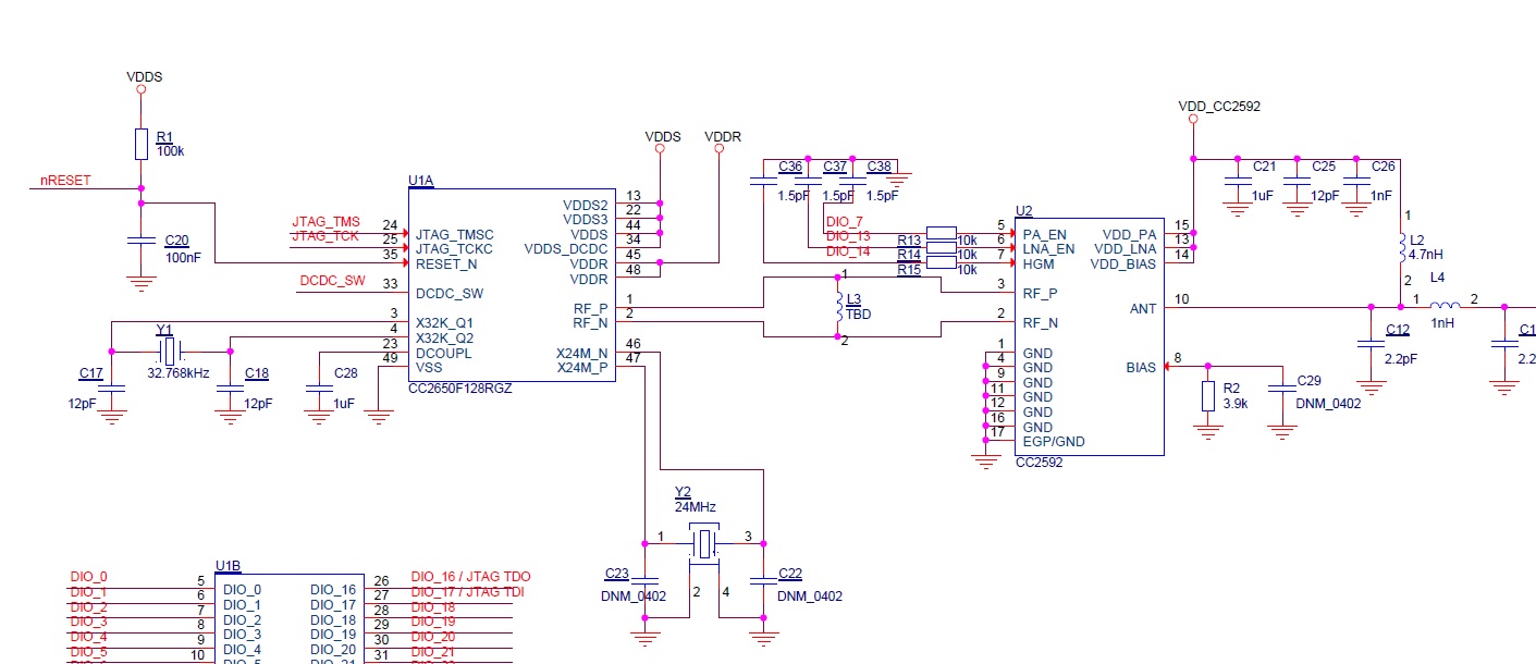
From the CC2592 datasheet the control logic for the pins are these below.

From the tidub71.pdf I need to configure these 3 GPIO DIO7, DIO13, DIO14 using this code below.
#include "ioc.h"
// Map RFC_GPO0 to DIO13
IOCPortConfigureSet(IOID_13, IOC_PORT_RFC_GPO0,
IOC_IOMODE_NORMAL);
// Map RFC_GPO1 to DIO7
IOCPortConfigureSet(IOID_7, IOC_PORT_RFC_GPO1,
IOC_IOMODE_NORMAL);
Then this is mentioned below:
"The settings to be programmed are 0x2F, 0x30, 0x31, 0x32 to get
RFC_GPO0, RFC_GPO1, RFC_GPO2, RFC_GPO3 respectively"\
Then this:
"DIO14 is initialized and programmed as a GPIO to provide HGM input for
CC2592. Registers configuration needed is as follows:
IOCFG7 = 0x30
IOCFG13 = 0x2F"
How exactly do I do all that? Do you have example program for CC2650-CC2592 EMK, so I can study it?
-kel


