This thread has been locked.

If you have a related question, please click the "Ask a related question" button in the top right corner. The newly created question will be automatically linked to this question.

CC2541: CC2541 stop to avertise for 2.9Hours and back to normal

Part Number: CC2541
Other Parts Discussed in Thread: CC2590, CC2540

Hello,  

 I'm developing Beacon module using the CC2541 and the CC2590.    

 The development environment is BLEstack 1.4.2.2 with using SimpleBLEBroadcaster -part of the CC2541. 

When the other related enginner completed the S/W,  it worked fine.   But when we did field test with more than 50 sets,   almost 100% of sets

stopped advertising  for 2.9Hours and get back to normal advertising condition.  It happened once per day or or once per week random.

Based on E2E advice,   I tried to adjust  (#define HAL_SLEEP_ADJ_TICKS) time to 85 from original 35 to secure enough 32MHz X-tal

stabilization time.   But the problem was happened contineously.   When I adjusted the tick time to 15,   the problem happened all the time.  

So I tried to excluded power_save mode as follow just for test.  Then I found 32MHz X-tal was running without sleep.   

 But the problem happened again  & again.     So it's thought that problem is not only related with Tick time. 

INT_HEAP_LEN=2048
HALNODEBUG
OSAL_CBTIMER_NUM_TASKS=1
HAL_AES_DMA=TRUE
HAL_DMA=TRUE
xPOWER_SAVING
xPLUS_BROADCASTER
xHAL_LCD=TRUE
xHAL_LED=FALSE
xHAL_KEY=TRUE

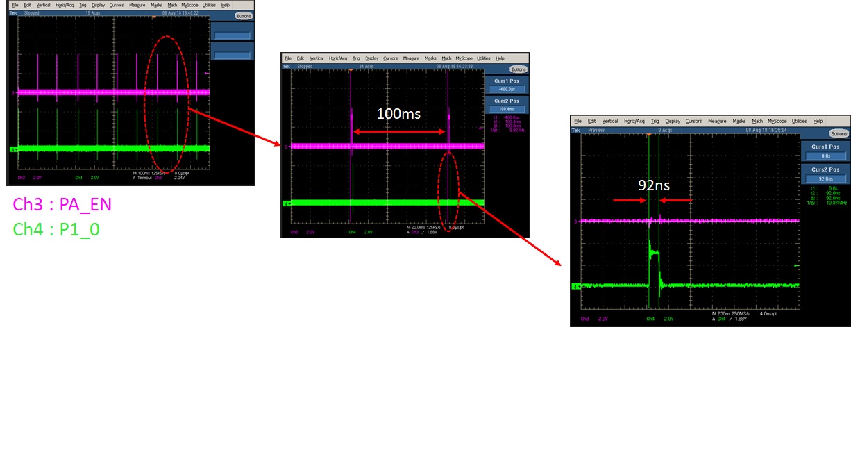
The other phenominon I found is that the problem cause 32MHz X-tal oscillation conteniously WHEN power_save mode was enabled.   

So normal power consumption 0.8mA was increased to 8mA for 2.9hours. And back to 0.8mA at sleep.  

To avoid any other unused I/O port interrupt,   I've changed port setting in many ways.    But it does not fix the problem.   

----------------------------------------------------------------------------------------------------

#if defined( CC2540_MINIDK )
 
  // Register for all key events - This app will handle all key events
  RegisterForKeys( simpleBLEBroadcaster_TaskID );
 
  // makes sure LEDs are off
  HalLedSet( (HAL_LED_1 | HAL_LED_2), HAL_LED_MODE_OFF );
 
  // For keyfob board set GPIO pins into a power-optimized state
  // Note that there is still some leakage current from the buzzer,
  // accelerometer, LEDs, and buttons on the PCB.
 
  P0SEL = 0; // Configure Port 0 as GPIO
  P1SEL = 0; // Configure Port 1 as GPIO
  P2SEL = 0; // Configure Port 2 as GPIO

  P0DIR = 0xFC; // Port 0 pins P0.0 and P0.1 as input (buttons),
                // all others (P0.2-P0.7) as output
  P1DIR = 0xFF; // All port 1 pins (P1.0-P1.7) as output
  P2DIR = 0x1F; // All port 1 pins (P2.0-P2.4) as output
 
  P0 = 0x03; // All pins on port 0 to low except for P0.0 and P0.1 (buttons)
  P1 = 0;   // All pins on port 1 to low
  P2 = 0;   // All pins on port 2 to low 
 
#endif // #if defined( CC2540_MINIDK )

----------------------------------------------------------------------------------------------------------------------------

Coul you pls advise which parts of S/W can cause such problem ?    And how to fix it ?  

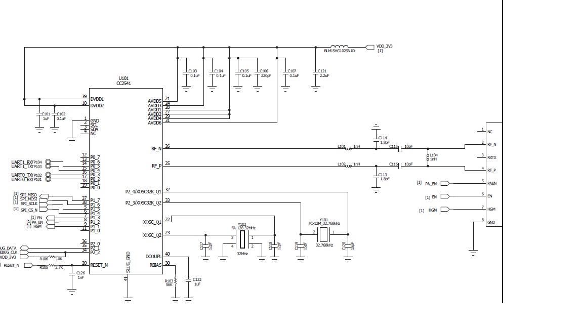
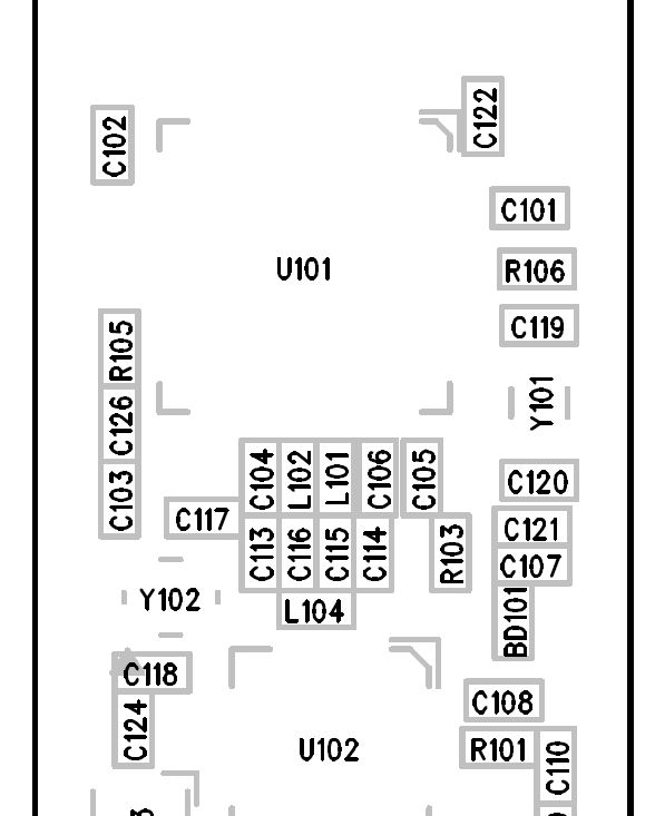
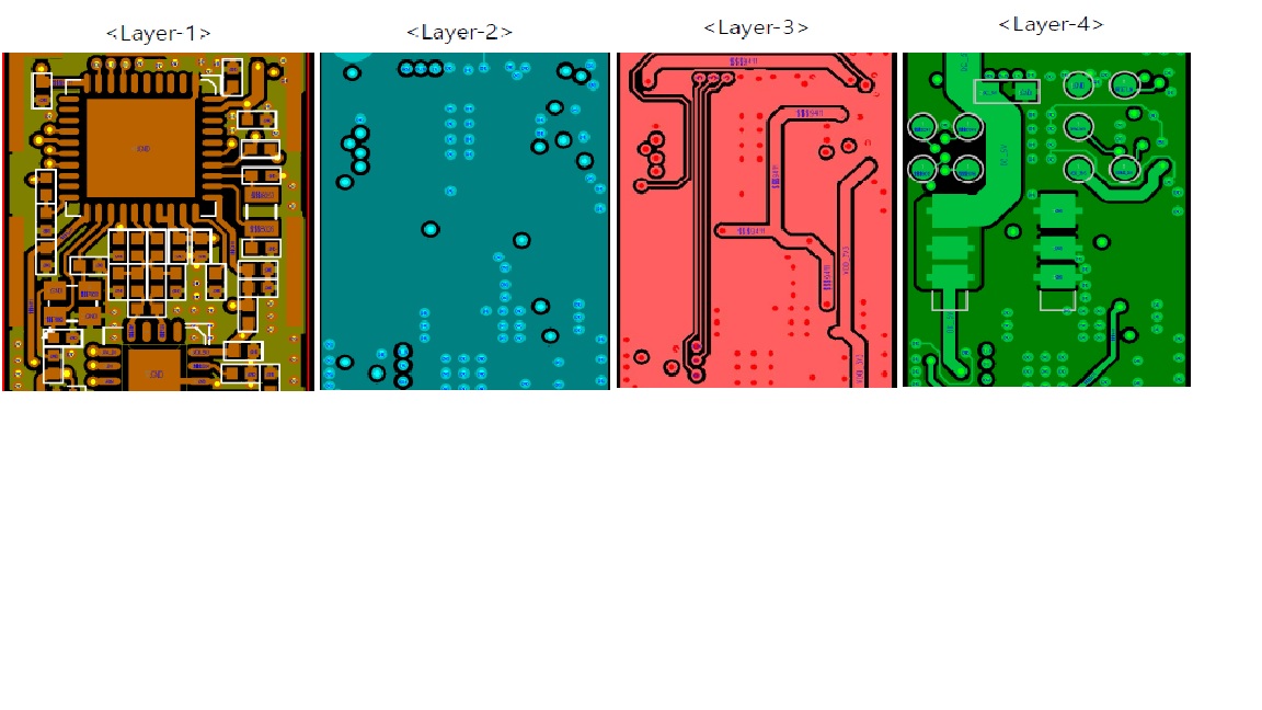
The schematic is as attached.  

 YS Kim


  • Hi,

    Can you add pin toggling under void osal_run_system( void ) in OSAL.c file?

    Original code:

      do {
        if (tasksEvents[idx])  // Task is highest priority that is ready.
        {
          break;
        }
      } while (++idx < tasksCnt);

    Pseudo code:

      do {
        if (tasksEvents[idx])  // Task is highest priority that is ready.
        {
    //if idx == 1, toggle once
    //if idx ==2, toggle twice
    //...
    //...
    //...
          break;
        }
      } while (++idx < tasksCnt);

    Then when the device stops advertising, can you connect a logic analyzer to capture the pin toggle for as long as possible?

  • Hi Christin,

    Thanks for your advice !


    I'm not so familar with CC2541 BLE stack.   But it looks like to find the taskevent  that causing the problem by Inserting the idx count toggle routine.    

    For normal case,   it looks to increase toggle count until  Taskcnt. 

    Since we don't use logic analyzer for several projects,   we don't have it now.   Will try to rent it and check what you said.      

    But the problem occurrence case is quite ramdom,   it may take a few days or more than 1 week to check it. 

    Until the test environment will be setup and result will come out,    I'd like to check somthing described in Hal_sleep.c  remark as follow.  

    In the remark,   there is a comment that timer 2 rollover could cause 2.9hours delay.   
    Since we setup advertse interval to 100msec,   we can see the RF radiation every 100msec with spectum analyzer.     

    But when problem was happened,   it take exactly 2.9hours (2hr 55min) to recover from the failure.      

    So even Max_sleep_Timeout was defined as 40sec,  and we use 100msec broadcating interval without connection,     

    any of variable parameter setting can cause the below timer overroll case?   
    Any critical point ?      

    And for the temporary solution,    if broadcasting is not done for more than 1sec-1min,   can we sniff it and reset the timer or

    reset whatever to recover the broadcasting ?     If it's possible,    could you pls provide the S/W routine and advise where to insert in?   

    My application is simplebroadcater without connection.    

    ------------------------------------------------------------------------------------------------------------
    // max allowed sleep time in ms
    // Note: When OSAL timer was updated to 32 bits, the call to halSleep was
    //       changed to take a 32-bit osal_timeout value. But since the CC2540
    //       previously used a 16 bit ll_McuPrecisionCount, halSleep was modified
    //       to limit osal_timeout to 16 bits as well (please see SVN rev. 27618).
    //       However, the max value of the 16 bit ll_McuPrecisionCount is about 41s,
    //       which is shorter than the max sleep time of 65.535s! So it is possible
    //       Timer2 rollover could occur during sleep, which could affect when an
    //       OSAL timer event is generated. The OSAL timer software should
    //       be updated to use the full 24bit value of Timer2, allowing timer
    //       events of up to 2.9 hours, but until this can be done properly, the
    //       max sleep duration will be limited to less than ll_McuPrecisionCount.
    // Note: Not an issue for BLE as the max sleep time would have to be less
    //       than 32s.
    #define MAX_SLEEP_TIMEOUT                   40000
    -------------------------------------------------------------------------------------------------------------- 

    YS Kim

  • Hi,

    Since you said the problem still exists when power saving is disabled, then it's unlikely sleep timer rollover is the issue.

    It would definitely be helpful if you can provide logic analyzer trace with what I have suggested.
  • Hi Christin,  

     Until the logic analyzer will be ready to record the log,  we measured the toggling with oscilloscope in normal

    advertising condition.    We inserted toggle count to idx + 1 to identify taskEvent [0]  also.   the outport is P1_0. 

    Since the advertising stop condition is not happenned easily (It take several day or more than 2 weeks),  

    we measured toggling at the normal advertsing status.   

    What we found is that only 1 toggle ( Taskevent [0] )  is serviced with 100msec interval.   

    And when we added 2 min timer based UART TX routine,   another 7 toggle (Taskevent [6])  was found 

    at every 2min together with 1 toggle.    When we make problem intentionally by touching X-Tal pin,  advertising was

    stopped.   But the 7 toggling  was happened at every 2min without 100msec interval 1 toggle (Taskevent[0]. 

    Even at this condition,   if 2.9hour is passed,  the advertising get back to normal.  

     -------------------UART test routine in simpleBLEBroadcaster.c-------------------------------------------------------------------------------------------------------

    static void performPeriodicTask( void )
    {

        uint8 current_adv_enabled_status;
        uint8 new_adv_enabled_status;
     
     new_adv_enabled_status = TRUE;
       
        //Find the current GAP advertisement status
        GAPRole_GetParameter( GAPROLE_ADVERT_ENABLED, &current_adv_enabled_status );
       
        if( current_adv_enabled_status == FALSE )
        {
            uart0Send(adv_status_off, sizeof(adv_status_off));
        }
        else
        {
           uart0Send(adv_status_on, sizeof(adv_status_on));
        }
       
        //change the GAP advertisement status to opposite of current status
        GAPRole_SetParameter( GAPROLE_ADVERT_ENABLED, sizeof( uint8 ), &new_adv_enabled_status );
      
    }

    ------------------------------------------------------------------------------------------------------------------------------------------------

    The above adv-status check routine was never stopped all the time.   But  do not output (adv_status_off) log when

    advertising was stopped.    always output (adv_status_on) regrardless actual adv_status.      

    FYI,  I added normal status waveform excluding UART code.        

    Of course,  we will continue to find toggling status on advertising failure condition with logic analyzer .     

    But it can take more than 2 weeks,   I'm posting what I found till now.   

    Just thinking it could be helpful,       Since we use CC2590 PA together,  we used PA_EN signal for triger point.


     YS Kim

  • Hi,

    Would you mind if we check your HW design schematic and layout? The problem is a bit weird since the timer wrap around is for sleep timer which when you disable PM, you should not observe the same.(Somehow you are still seeing it...)
  • Hi Christin,  

     Pls refer to the attached PCB gerber files.  

    Since I already uproaded sch file in previous posting,   I'm posting PCB related files only at this time.

    U101 is CC2541 and U102 is CC2590.   1pin of each parts are located to upper right position.   Y101 is 32.768KHz RTC and Y102 is

    32MHz X-tal.   And dark green color of layer1 is copper plane connected to GND.    Since we refer to the CC2541-CC2590 ref design, 

    the schematic and PCB file will be almost same with the TI ref design.         

    Regarding the test ongoing  now,   we just focused on  Power_save mode disabled.   

    Even we encountered 2.9Hour adv stop failure condition about few weeks ago,   current testing do not show the failure for 1week. 

    It's monotored by current consumption log and digital storage scope log.    But as I said it can be happened once per 2weeks, 

    we will continue the test 1 or 2 weeks more.   I'm not sure why power_save mode disabled test showed failure winthin 1 day when  

    we did the test several weeks ago.      the changed code is only UART monitoring routine.  


    Regarding to the logic analyzer,    Any recommended model for rental ?   

    According to my survey,   in case of 20MHz-32MHz signal capture,   the waveform can not be stored in big storage SSD or

    HDD contineously.  It should be captured the RAM inside of logic analyzer due to speed.   Then we can not save the waveform

    for 2-3weeks until the failure will be happened.    If we extend the toggling duration by inserting several 'NOP' to secure the time required

    to store the signal data in SSD or HDD  of Logic analyzer or PC,  it can be a big obstacle for timing critical Link Layer or other event

    processing.             To avoid those kind of restriction,  the logic analyzer need to have programmable triger & capture function.   

    It's because we need to capture the waveform when toggling count or pattern was changed from normal toggling.   

    Nomal logic analyzer have only edge & level triger function per channel.   It's difficult to find such model that can program the triger

    condition when the pulse count or pattern was changed during the desired interval.    


    YS Kim

  • Hi Christin,  

     The failure for 2.9Hr was happened again.     

    Due to the difficulty of selecting logic analyzer,  We captured with 1GHz scope using the conditional capture when no triger signal is happend for 120msec.        

    The test condition is power_save mode disabled.      

    What I see and Important factor is ;

     1. Before it goes to fail,  Even PA_EN signal is generated normally.  But the  osal_run_system( void ) in OSAL.c  was not routed.  (No toggle as below).

     2. After 100msec have passed,  the PA_EN signal was generated.   And S/W get into  osal_run_system( void ) in OSAL.c again.   (toggle was found)

     3. And advertising stopped with no PA_EN & toggle for 2.9Hours.     And get back to normal.        

    If you see below picture,   you will find this.    But due to scope's storage limit,   we couldn't zoom in how many toggle was happened before it stopped.

    We have purchase 25kset of CC2541 /CC2590 on hand.  and 5ksets was on buyer's hand,   and got serious blame from old buyer.  

    I'm loking for you and TI engineers' strong attention to fix it.       If needed,  I'll forward the whole source code for you to verify and fix.  

    Then let me know the e-mail address to send the whole code.    Since the problem was happened 2 months ago,   It's urgent !!                

    YS Kim


  • Hi,

    Will it be possible for you to implement a watchdog and reset the system is there is one missing adv event?(pat the watchdog at the end of every adv interval)

    Our HW team has checked the design and it seems to be ok.

    Does your SW need to be run on custom HW?
  • Hi Christin,  

     Since the delay was serious,    I already implemented watch dog timer reset routine, when event is not occurred during 1sec.  

    And found the system is going well without fault.       

    Even the wach dog reset is happened,   the originally generated random address shouldn't be changed,  I tried to put the address

    data to flash memory as be described in OSAL.API.     But after watch dog reset is happened,   the flash contents canged to 0x00 value.

    Of course,   I inserted conditional ramdom number seed like  "if ((SLEEPSTA & 0x18) != 0x10)".

    But as soon as the watch dog reset was generated,  the flash contents was disappeared when I make a break point in 1st function call in main() .   

    Of course, verified by using OSAL.API  SNV read routine.  

    So I saved the Radom address in RAM  and used   __no_init uint8 randomaddr[4];   by defining glabal variable.    Then it worked.  

    But why OSAL SNV reading cause '0x00'   after watchdog reset ?    Of courrse I verified writed & read was OK in SimpleBLRBroadcaster.c  

    when I set the break point  after reading.     

     The below is the SNV_read/ write routine that I tested using several method.   Worked well but disappeared after WDT rest.  

    //////////////////////////// 

      WD_KICK();
      if (SUCCESS != osal_snv_read((osalSnvId_t) SNV_ID_APP, (osalSnvLen_t) Buf_Len, advertData))
     
       {
        uint8 fail = advertData[25];
     
        halIntState_t _s;
        HAL_ENTER_CRITICAL_SECTION(_s);   
        osal_snv_write((osalSnvId_t) SNV_ID_APP, (osalSnvLen_t) Buf_Len, advertData);
        HAL_EXIT_CRITICAL_SECTION(_s);  

        uint16 waitx; 
        for (waitx =0; waitx < 60000 ; waitx++)
        {
          waitx = waitx ;
        }
         
     
      if (SUCCESS != osal_snv_read((osalSnvId_t) SNV_ID_APP, (osalSnvLen_t) Buf_Len, advertData))
           {
          uint8 fail = 0x44;    
           } 
          uint8 dd = advertData[25];
          uint8 cc = advertData[26];
       }
       // added by YSK  Aug/19/'18 -wdt ctl 
     }

         WD_KICK();
         osal_snv_read((osalSnvId_t) SNV_ID_APP, (osalSnvLen_t) Buf_Len, advertData);
    //   osal_snv_read((osalSnvId_t) 0x80, (osalSnvLen_t) 0x4, pBuf);

    /////////////////////////////

    FYI, 

    I measured the malfanction task event using Saleae logic analyzer by making intentional WD reset by touching RTC X-tal long time.  

    You may download the Saleae logic analyzer program in the web site by free.     

    It looks this web do not support file name "24 MHz, 720 M Samples [7]6.logicdata".      I cannot upload.    

    YS Kim

  • It seems like the write is not successful in this case.

    Are you generated random address in your application? Can you send me your full source? I am not following what you said regarding the address here.

    You can send me the source through e2e message box.
  • Pls refer to the below  random number seeding & writing it to SNV & and read from SNV.   

    There are several debug purpose line.    It's just to check whether writing & reading was OK or not.  

    /////////////////////////////////////////////////////////////////////////////////////////

    void SimpleBLEBroadcaster_Init( uint8 task_id )
    {
    //  static uint8 ownAddress[B_ADDR_LEN];
      simpleBLEBroadcaster_TaskID = task_id;
     
    #define Buf_Len 29
    #define SNV_ID_APP 0x80
     
    if ((SLEEPSTA & 0x18) != 0x10)  //  If reset was not generated by WDT,  proceed ramdom number seed routine as follow. 
     {
      uint16 seed = Onboard_rand();
      advertData[25] = randomaddr[0] = HI_UINT16(seed);//major_h
      advertData[26] = randomaddr[1] = LO_UINT16(seed);//major_l

      seed = Onboard_rand();
      advertData[27] = randomaddr[2] = HI_UINT16(seed);//minor_h
      advertData[28] = randomaddr[3] = LO_UINT16(seed);//minor_l
     

                                    uint8 dd = advertData[25];
    breakpoint here -->  uint8 cc = advertData[26];


      WD_KICK();
      if (SUCCESS != osal_snv_read((osalSnvId_t) SNV_ID_APP, (osalSnvLen_t) Buf_Len, advertData))
     
       {
        uint8 fail = advertData[25];
     
        halIntState_t _s;
        HAL_ENTER_CRITICAL_SECTION(_s);   
        osal_snv_write((osalSnvId_t) SNV_ID_APP, (osalSnvLen_t) Buf_Len, advertData);
        HAL_EXIT_CRITICAL_SECTION(_s);  

        uint16 waitx; 
        for (waitx =0; waitx < 60000 ; waitx++)   // just wat if SNV writing requires time. 
        {
          waitx = waitx ;
        }
         
     
      if (SUCCESS != osal_snv_read((osalSnvId_t) SNV_ID_APP, (osalSnvLen_t) Buf_Len, advertData))
           {
          uint8 fail = 0x44;    
           } 
          uint8 dd = advertData[25];
          uint8 cc = advertData[26];
       }
       // added by YSK  Aug/19/'18 -wdt ctl 
     }

         WD_KICK();
         osal_snv_read((osalSnvId_t) SNV_ID_APP, (osalSnvLen_t) Buf_Len, advertData);


                                    uint8 dd = advertData[25];
    breakpoint here -->  uint8 cc = advertData[26];


    // At this point.  verified that advertData writing & reading looks to be OK.   But not sure whether it's written & read at proper location with above routine.  
    Anyway when I read, dd & cc ,  it was original generated ramdom data as breakpoint set above.   But after watchdog reset,  it was read to 0x00.  
    So replaced  advertData[] to non_init randomaddr[]  finally to fix the issue quickly.    


         advertData[25] = randomaddr[0]; 
         advertData[26] = randomaddr[1];
         advertData[27] = randomaddr[2];
         advertData[28] = randomaddr[3];
     
     GAPRole_GetParameter(GAPROLE_BD_ADDR, BdAddress);

     randomaddr[4];LL_ReadBDADDR(BdAddress);
     
     scanRspData[11] = BdAddress[5];
     scanRspData[12] = BdAddress[4];
     scanRspData[13] = BdAddress[3];
     scanRspData[14] = BdAddress[2];
     scanRspData[15] = BdAddress[1];
     scanRspData[16] = BdAddress[0]; 

    ////////////////////////////////////////////////////////////////////////////////////////////////////////////////////

    YS Kim


  • In your code, I would recommend you to read back after you do a write and compare the content before you move away from the initialization phase.

    Also make sure you get a SUCCESS in return when you execute a snv_write.

    Please read back the whole flash image before and after snv_write so that we can see what has been written.

  • There maybe a possiblility that I did a mistake at somewhere in the SNV code handling.   

    Since I'm doing another urgent project while it's resolved by uninitializing the RAM,   I may look into more detail when I can go back to CC2541.

     But it looks like that 8051 core related CC2541 documentation is not so detail and lack of sample codes compared MSP430 or other products.  

    Anyway,  thank you for your help !

    YS Kim