This thread has been locked.

If you have a related question, please click the "Ask a related question" button in the top right corner. The newly created question will be automatically linked to this question.

CCS/CC2640R2F: Strange behavior of I2C read write.

Part Number: CC2640R2F

Tool/software: Code Composer Studio

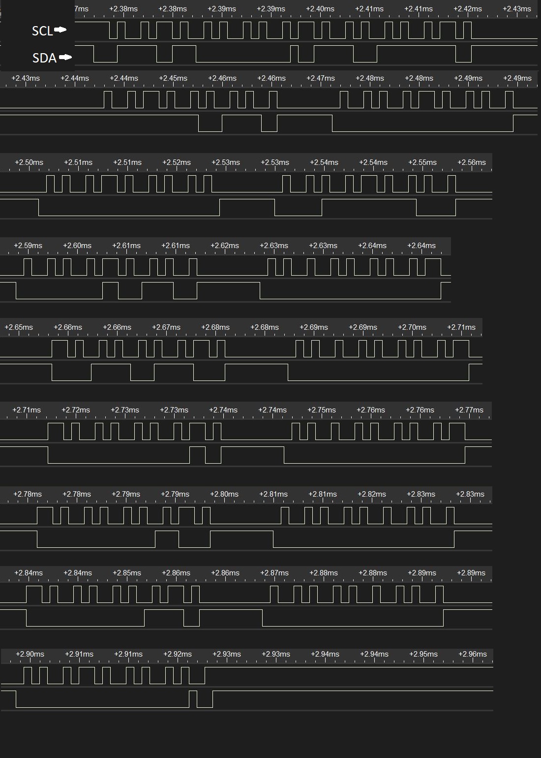
Hello, My objective is to implement DMP-MPU9250 library for CC2640R2F. I have ported DMP library and it is initializing but getting i2c read error when i write read data from MPU8250 memory. if I am reading or writing single or double byte data then no issue it's working fine. But whenever I try to read multiple bytes 8 of 16 bytes I get the wrong Bytes. Sometimes I get shifted bytes.  

for example, I am writing the following bytes in MPU9250 memory                                                                                                                                                                                     0x00, 0x00, 0x70, 0x00, 0x00, 0x00, 0x00, 0x24, 0x00, 0x00, 0x00, 0x02, 0x00, 0x03, 0x00, 0x00,                                                                                                   

but when i read i found following bytes.                                                                                                                                                                                                                                             0xb1 0x94 0x9a 0xe5 0x0 0x0 0x70 0x0 0x0 0x0 0x0 0x24 0x0 0x0 0x0 0x2       

i2c_write(st.hw->addr, st.reg->mem_r_w, length, data)    function for raeding bytes                                                                                                                                                          i2c_read(st.hw->addr, st.reg->mem_r_w, length, data)  function for writting bytes

So, you may clearly see that i am getting 4 error bytes. following is my i2c implementation file.

i2c_rutinas.c
Fullscreen
1
2
3
4
5
6
7
8
9
10
11
12
13
14
15
16
17
18
19
20
21
22
23
24
25
26
27
28
29
30
31
32
33
34
35
36
37
38
39
40
41
42
43
44
45
46
47
48
49
50
51
52
53
54
55
56
57
58
59
60
61
62
63
64
65
66
67
/* -----------------------------------------------------------------------------
* Mis includes
* ------------------------------------------------------------------------------
*/
#include "i2c_rutinas.h"
//#include "std.h"
/* -----------------------------------------------------------------------------
* Cosas de I2C
* ------------------------------------------------------------------------------
*/
static volatile uint8_t slaveAddr; //dispositivo a escribirle
static volatile uint8_t interface; //I2c 0 o 1
static const I2CPinCfg pinCfg1 ={
.pinSDA = CC2640R2_LAUNCHXL_I2C0_SDA0,
.pinSCL = CC2640R2_LAUNCHXL_I2C0_SCL0}; //Config custom para interfaz 1
static I2C_Handle i2cHandle; //Instancia de handle
static I2C_Params i2cParams; //Instancia de par�metros
uint8_t buffer[32];
/*******************************************************************************
* @fn i2c_write
* @brief Escribe por i2c, adaptada para driver
* @param pbuf - Puntero al Buffer
* @param nBits - N�mero de bits
* @return !ok
*/
bool i2c_write(uint8_t slave_addr, uint8_t reg_addr, uint8_t length, uint8_t *data)
{
slaveAddr=slave_addr;
uint8_t i;
uint8_t *p = buffer;
//reg y dato al buffer
*p++ = reg_addr;
for (i = 0; i < length; i++)
{
*p++ = *data++;
}
length++;
return !i2c_escribe(buffer,length);
}
/*******************************************************************************
* @fn i2c_read
* @brief Lee por i2c, adaptada para driver
* @param pbuf - Puntero al Buffer
* @param nBits - N�mero de bits
* @return !ok
*/
bool i2c_read(uint8_t slave_addr, uint8_t reg_addr,uint8_t length, uint8_t *data){
slaveAddr=slave_addr;
return !i2c_escribe_lee(&reg_addr,1,data,length);
}
uint8_t rd[100] = {0};
bool work = 0;
bool i2c_readShift(uint8_t slave_addr, uint8_t reg_addr,uint8_t length, uint8_t *data)
{
slaveAddr=slave_addr;
work = i2c_escribe_lee(&reg_addr,1,rd,length+4);
uint8_t ln = 0;
for(ln = 0;ln<length;ln++)
XXXXXXXXXXXXXXXXXXXXXXXXXXXXXXXXXXXXXXXXXXXXXXXXXX

i2c_rutinas.h

I am using

1)  CC2640R2F Launchpad                               2) BLE 4.2   and Ble stack sdk simplelink_cc2640r2_sdk_1_50_00_58                                                                                                       3) Code composer studio version 8.0.0              4) Ti Compiler version 16.9.6

Thank You

Pradeep

  • Hi Pradeep,

    Have you tried to scope the signals and see if you are actually writing and reading what you expect to the device itself?
    If you can verify that you indeed write what you expect and that the data you read out is what you also see in SW, then I would look into why the MPU9250 is sending you this data.
  • Hi, yes i verified by using the scope also.

    I am writing  bytes at sub-address  0x68 and register address MPU9250_RA_MEM_R_W  0x6F

    0xfb 0x0 0x0 0x3e 0x0 0xb 0x0 0x36 0x0 0x1 0x0 0x2 0x0 0x3 0x0 0x0

    but when i read i found following value

    0x9c  0xfb 0x0 0x0 0x3e 0x0 0xb 0x0 0x36 0x0 0x1 0x0 0x2 0x0 0x3 0x0

    so you can see getting one extra bytes. Now the thing is that this is not consistent sometimes i am getting one sometimes two extra bytes or 4 bytes. So this is creating problem for me while implementing DMP. Following is the scope image for read write of above bytes.

    i2c write.

    i2c read

    Thank You.

  • Hi Pradeep,

    If what you are writing to the device is what you expect, and you can verify that what you read in SW is what actually is sent on the physical medium, then the problem most likely is with how you are using the other device. If the MPU sends you the unexpected data then I would start to look into why it is doing so.

    You could start with trying to lower the bitrate and see if it makes a difference. I don't know if it is the scope you are using or the hardware but the SCL line does seem a bit irregular.
  • Actully the issue is with large bytes like 16 or 20 bytes only. If i am writing and reading 4 or bytes then its working fine. Because if i am accessing the accelerometer or gyrometer data by using its register then i am getting correct data, but if i am using fifo register of mpu to read values then this error is happening. And for using fifo we have to write mpu9250 dmp firmware. But to i2c error i am unable to this.

    I am using Hanket 6022BL oscilloscope for verifying.
    Thank You
  • Hi Pradeep,

    I understand that this is a problem, but if you can verify that the data going out of the CC2640R2 is what you expect and that the data you read back is not (on bus level this is) then I can't really give you any other advice then to look into if you are doing your dmp parts right.

    If the I2C driver is sending what you expect and reading what you see on the bus, then the source of the data is the issue and not the driver itself. I would look into timing requirements for the device and make sure you match all of these as expected. Also, did you try to lower the bitRate?
  • OK I will check these things once again and then I'll get back to you within an hour.
    Thank You

  • Sir, I verified by setiing i2c frequency from 400khz to 100khz there is no effect, getting same result.
    I verified by writing and reading all the registers values and compared with the Arduino also. So i2c is working fine till, MPU9250 DMP code write to MPU9250 memory after this I am getting error. Following is log of my project
    Thank You

    [Cortex_M3_0] i2c initialized
    MPU9250_RA_WHO_AM_I 0x75 register read 0x71
    connection successful
    setting PLL with X Gyro reference MPU9250_CLOCK_PLL_XGYRO= 0x01
    MPU9250_RA_PWR_MGMT_1 0x6B register write 0x1
    MPU9250_RA_PWR_MGMT_1 0x6B register read 0x1
    setting gyro full range
    MPU9250_RA_GYRO_CONFIG 0x1B register write 0x18
    MPU9250_RA_GYRO_CONFIG 0x1B register read 0x18
    sleep enable
    MPU9250_RA_PWR_MGMT_1 0x6B register write 0x1
    MPU9250_RA_ACCEL_CONFIG 0x1C register read 0x1
    DMP INITIALIZING
    reset MPU9250
    reset MPU9250_RA_PWR_MGMT_1 0x6B write 0x80
    reset MPU9250_RA_PWR_MGMT_1 0x6B read 0x1
    sleep enable
    MPU9250_RA_PWR_MGMT_1 0x6B register write 0x1
    MPU9250_RA_ACCEL_CONFIG 0x1C register read 0x1
    select memory bank BAnk
    Bank select MPU9250_RA_BANK_SEL 0x6D register write 0x70
    Bank select MPU9250_RA_BANK_SEL 0x6D register read 0x70
    select memory start address
    memory start MPU9250_RA_MEM_START_ADDR 0x6E register write 0x6
    memory start MPU9250_RA_MEM_START_ADDR 0x6E register read 0x6
    hwRevision 0
    Resetting memory bank selection to 0...
    Bank select MPU9250_RA_BANK_SEL 0x6D register write 0x0
    Bank select MPU9250_RA_BANK_SEL 0x6D register read 0x0
    otp valid 1
    USER CTRL 0
    Enabling interrupt latch, clear on any read, AUX bypass enabled
    interrupt config MPU9250_RA_INT_PIN_CFG 0x37 register write 0x32
    interrupt config MPU9250_RA_INT_PIN_CFG 0x37 register read 0x32
    Setting magnetometer mode to power-down...
    0x0A register write 0x0
    0x0A register read 0x0
    adjusted value 0 0 0

    Writing DMP code to MPU memory banks
    MPU9250_DMP_CODE_SIZE 1962
    select memory bank BAnk
    Bank select MPU9250_RA_BANK_SEL 0x6D register write 0x0
    Bank select MPU9250_RA_BANK_SEL 0x6D register read 0x0
    select memory bank start address
    select memory start address
    memory start MPU9250_RA_MEM_START_ADDR 0x6E register write 0x0
    memory start MPU9250_RA_MEM_START_ADDR 0x6E register read 0x0

    writting 16 byte DMP code to MPU9250_RA_MEM_R_W 0x6F register
    0xfb 0x0 0x0 0x3e 0x0 0xb 0x0 0x36 0x0 0x1 0x0 0x2 0x0 0x3 0x0 0x0

    Bank select MPU9250_RA_BANK_SEL 0x6D register write 0x0
    Bank select MPU9250_RA_BANK_SEL 0x6D register read 0x0
    select memory start address
    memory start MPU9250_RA_MEM_START_ADDR 0x6E register write 0x0
    memory start MPU9250_RA_MEM_START_ADDR 0x6E register read 0x0

    Reading 16 byte DMP code written to MPU9250_RA_MEM_R_W 0x6F register
    0xda 0xfb 0x0 0x0 0x3e 0x0 0xb 0x0 0x36 0x0 0x1 0x0 0x2 0x0 0x3 0x0

    BUFFER VERIFyingBlock write verification error, bank
    0 address 0!
    Expected: 0xfb 0x0 0x0 0x0 0x0 0x3e 0x0 0x0 0x0 0xb 0x0 0x0 0x36 0x0 0x0 0x0 0x1 0x0 0x0 0x0 0x2 0x0 0x0 0x0 0x3 0x0 0x0 0x0 0x0
    Received: 0xda 0xfb 0x0 0x0 0x0 0x0 0x3e 0x0 0x0 0x0 0xb 0x0 0x0 0x36 0x0 0x0 0x0 0x1 0x0 0x0 0x0 0x2 0x0 0x0 0x0 0x3 0x0 0x0

    setup complete

  • Sir, now the situation is that. I found 3-4 DMP code for Arduino. So initially I ported this i2cdev DMP github.com/.../MPU9250 library. But I stuck got above error. So I thought there may issue with porting because at that time I was not know taht it's byte read write error. Then I ported invensese DMP motion library 6.12 and sparkfun DMP lirary github.com/.../SparkFun_MPU-9250-DMP_Arduino_Library also. In all these three library I am getting above error. If I am reading accelerometer or gyro value using MPU9250 defined registers then I can get these values, but for running invensense DMP fusion algorithm first we have to write invensense DMP firmware code to MPU9250. And that is creating issue.

    Thank You

  • As I have already send my i2c.c and i2c.h files. And if these files are correct then I can't understand why I am getting this issue

  • Hi Pradeep,

    As i mentioned before, this sound like an issue in the porting rather then an actual I2C issue. Unless you can't pin-point what the issue would be with the I2C driver I'm not able to help you resolve this.

    How you program the DMP and how you verify the code is better asked to Invensense as they know what sequence makes sense or not.
  • Hi, i ported the MPU9250 DMP library successfully  And now DMP is working with CC2640R2F . Thanks for the support.