This thread has been locked.

If you have a related question, please click the "Ask a related question" button in the top right corner. The newly created question will be automatically linked to this question.

CC2642R: communication I/Fs between External MCU and TI CC2642

Part Number: CC2642R
Other Parts Discussed in Thread: UNIFLASH

Hi TI experts

  1. SPI related things.
  • CC2642 will be acted as SPI slave to communicate with an external MCU.
    • I understood that there are 3-methods to implement SPI communication using TI-RTOS based legacy SPI driver, TL(Transport Layer) based on NPI(Network Processor Interface), and Bit-banging based on Sensor Controller block engine.
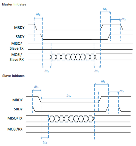
    • By the way, when using TL based approach, SDRY pin is needed to support the flow-control and power saving mode. is the SCLK still necessary, so totally, MRDY, SRDY, MISO, MOSI, SCLK, without CSN.
      • Is there no problem if MRDY could be multiplexed with CSN in terms of HW and SW point-view?
      • There is no pulse with respect to SCLK you posted to TI Wiki or Forum. Only MRDY, SDRY, MISO, MOSI pulses are there. Is the SCLK not being used? Just no pulse on the diagram picture?


  • When using TI-RTOS based legacy SPI Driver,
    • Are still MRDY, SRDY necessary to support the flow-control and power saving mode?


  • TI-RTOS legacy SPI driver or TL? Which is better to integrate the Host_Test App for DTM I/F along with BLE peripheral role for only OTA upgrade and BLE central role.
    • The Host_Test app uses the TL method. And it seems to be not big from code-wise.
    • What is your recommendation?


  • CC2642 will have an external flash.
    • OTA off-chip feature will be used.
    • Also, we are thinking of the ROM-based serial bootloader for a new FW image upgrade. For this, is the backdoor PIN needed and mandatory?  
      • If ROM-based serial bootloader is possible, do we have to use the fixed and dedicated pins(DIO8 to DIO11 on 7x7 package)? Right?
    • Can you check if the below procedure is right or not to support the ROM-based bootloader mode?
      • 1. External MCU requests a FW upgrade with a specific command.
      • 2. CC2642 based SW will issue the backdoor enable sequence through updating the CCFG and force to system reset.
      • 3. When the backdoor dedicated pin is matched with the assert condition, CC2642 enters the ROM-based on serial bootloader mode.
      • 4. External MCU will update a FW image according to the FW upgrade process.
      • 5. External MCU will force to reset CC2642.


         2. UART related things,

  • We are using LIN communication on DIO2 & DIO3.
    • With this above condition, there is no problem for the TI SmartRF programmer to program a new FW image. It seems to be no conflict so far? Could it be still kept valid?


        3. The TI SFW(Secure FW) upgrade method along with the ROM-based serial bootloader.

  • If FW upgrade get failed, current TI SFW method doesn’t have recovery mechanism.
  • Only backdoor method or else to recover it?


         4. Code protection like JTAG I/F

  • When code protection is executed, is ROM-based serial bootloader method also disabled?
  • How to disable the code protection mode when some repairing or updating issues arise after product released?
  • Only OTA is eligible for FW upgrade? Is it possible to upgrade FW image by using TI Smart RF programmer or Uniflash tool?


BR,

Ji-won Lee

  • Hi Ji-Won

    Is there no problem if MRDY could be multiplexed with CSN in terms of HW and SW point-view?


    This would depend on the situation, in most of our examples there is no "actual CSN" set which means the SPI Slave is always active and listening for data.
    If you are using the same interface for multiple slaves, this could cause a problem on SW level if you don't assign a dedicated CSN for the slave.

    A common issue is that MRDY is miss-interpreted as CSN which causes SW confusion when the same bus is used for multiple slaves as data is still received
    even if MRDY is not set. If there is only one device (the CC2642 in this case) that uses the MRDY signal you should be OK without CSN as long as you know
    the SCLK is not running.

    If you want to have a CSN, you could use the MRDY for this. Keep in mind that one physical pin can only be multiplexed to one peripheral at a time which means
    you would need to split the signal to two physical pins on the CC2642 side to avoid SW conflicts accessing the same pin. 

    There is no pulse with respect to SCLK you posted to TI Wiki or Forum. Only MRDY, SDRY, MISO, MOSI pulses are there. Is the SCLK not being used? 
    J
    ust no pulse on the diagram picture?

    In this diagrams, SCLK is implicit. You still need the SCLK signal.

    When using TI-RTOS based legacy SPI Driver, are still MRDY, SRDY necessary to support the flow-control and power saving mode?

    The standard TI-RTOS SPI driver does not implement any flow-control features such as MRDY and SRDY handshakes. Any needs for flow-control would have
    to be managed by the application together with the power saving logic.

    TI-RTOS legacy SPI driver or TL?

    I would say this depends on your needs, if you need the TL features and are OK with the code size you could go with that.
    If you go with using the standard SPI driver you would have to implement the TL features yourself if you need it, you do however have more control of the logic
    and can better adjust it for your needs.

    CC2642 will have an external flash. OTA off-chip feature will be used. Also, we are thinking of the ROM-based serial bootloader for a new FW image upgrade.
    For this, is the backdoor PIN needed and mandatory? 
    If ROM-based serial bootloader is possible, do we have to use the fixed and dedicated pins(DIO8 to DIO11 on 7x7 package)? Right?

    Can you check if the below procedure is right or not to support the ROM-based bootloader mode?

      • 1. External MCU requests a FW upgrade with a specific command.
      • 2. CC2642 based SW will issue the backdoor enable sequence through updating the CCFG and force to system reset.
      • 3. When the backdoor dedicated pin is matched with the assert condition, CC2642 enters the ROM-based on serial bootloader mode.
      • 4. External MCU will update a FW image according to the FW upgrade process.
      • 5. External MCU will force to reset CC2642

    To use the ROM serial bootloader to update a device that contains an valid image, the backdoor need to be enabled and used. You are correct in that you would
    need to use the device dedicated pins (DIO8-DIO11).

    The first two steps of the sequence is something you want to avoid. It is not recommended changing the CCFG section in run-time. If you want to use the ROM-based
    bootloader this should be enabled in CCFG from start. This does however leave the device open for reading out the flash.

    If you need something similar to the steps above you can use a flash based bootloader which you can modify to your needs.

    We are using LIN communication on DIO2 & DIO3. With this above condition, there is no problem for the TI SmartRF programmer to program a new FW image.
    It seems to be no conflict so far? Could it be still kept valid?

    If I understand you correctly here, you should be ok, the ROM-bootloader selects the interface that is first accessed externally as the interface to use.
    The same backdoor restrictions apply. 

    If FW upgrade get failed, current TI SFW method doesn’t have recovery mechanism. Only backdoor method or else to recover it?

    The TI SFW does not feature any recovery mechanism as you say. To recover from a failed image download, you would have to re-program the device with a
    valid image.

    When code protection is executed, is ROM-based serial bootloader method also disabled? How to disable the code protection mode when some repairing or
    updating issues arise after product released? Only OTA is eligible for FW upgrade? Is it possible to upgrade FW image by using TI Smart RF programmer
    or Uniflash tool?

    If you by code protection means disabling JTAG then this would not also disable serial bootloader. If simply the JTAG interface is locked, you can still erase and reprogram
    the device. There is further options you can enable to disable flash erase request from either the serial bootloader or JTAG interface. If these are also set then there is no way
    to access the device after the initial programming. In this case, possible OTA upgrades could be an alternative unless you are using your own bootloader.