This thread has been locked.

If you have a related question, please click the "Ask a related question" button in the top right corner. The newly created question will be automatically linked to this question.

SIMPLELINK-CC2640R2-SDK: v2.30: Not able to pass Sensor Controller LSM303AGR Accelerometer + Magnetometer data to Main Application?

Part Number: SIMPLELINK-CC2640R2-SDK
Other Parts Discussed in Thread: CC2640R2F, OPT3001, LAUNCHXL-CC2640R2

Hi,

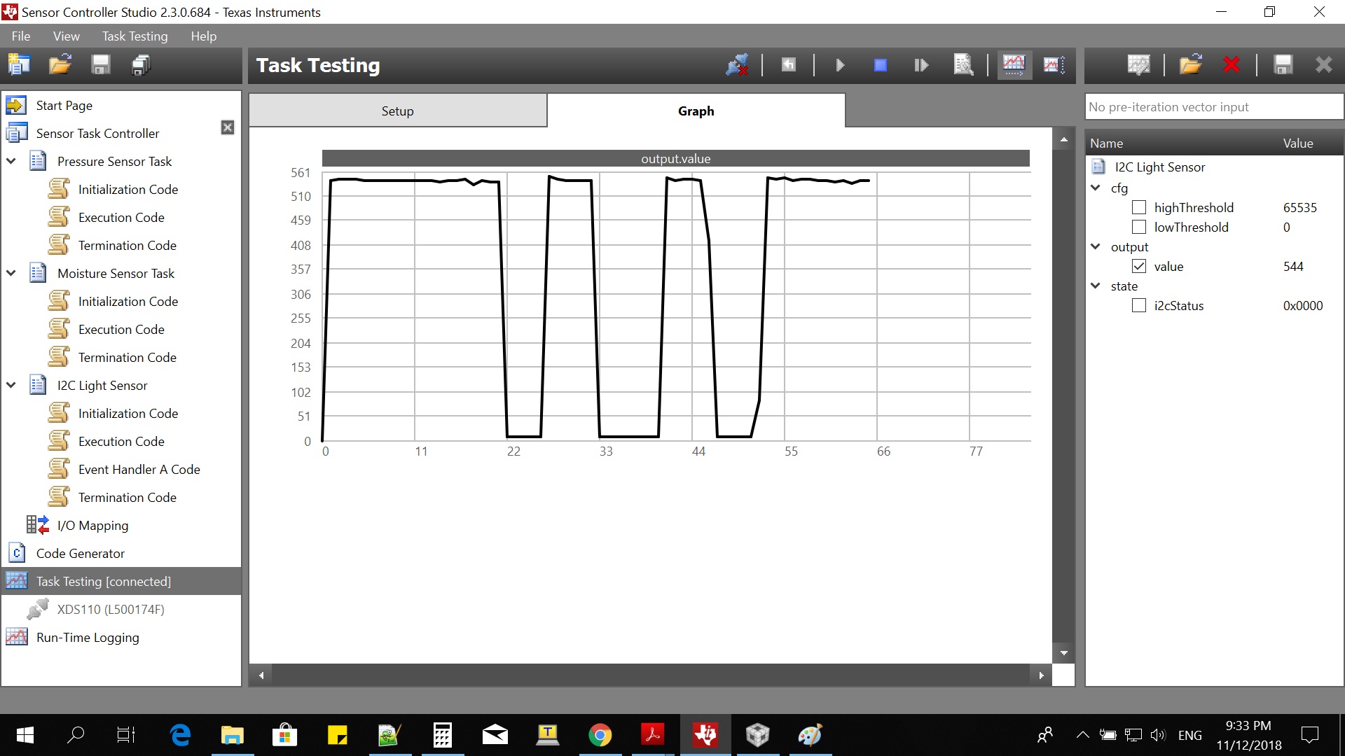
   I am using a 4x4mm CC2640R2F Custom Board with Pressure Sensor, Humidity Sensor and LSM303AGR Sensor. I am using Sensor Controller to read all the sensors. I am able to pass Pressure Sensor Data and Humidity Sensor Data from Sensor Controller to Main Application. However when I pass LSM303AGR Accelerometer + Magnetometer Sensor Data to Main Application I am getting 0. The LSM303AGR Sensor Controller Task works, see below.
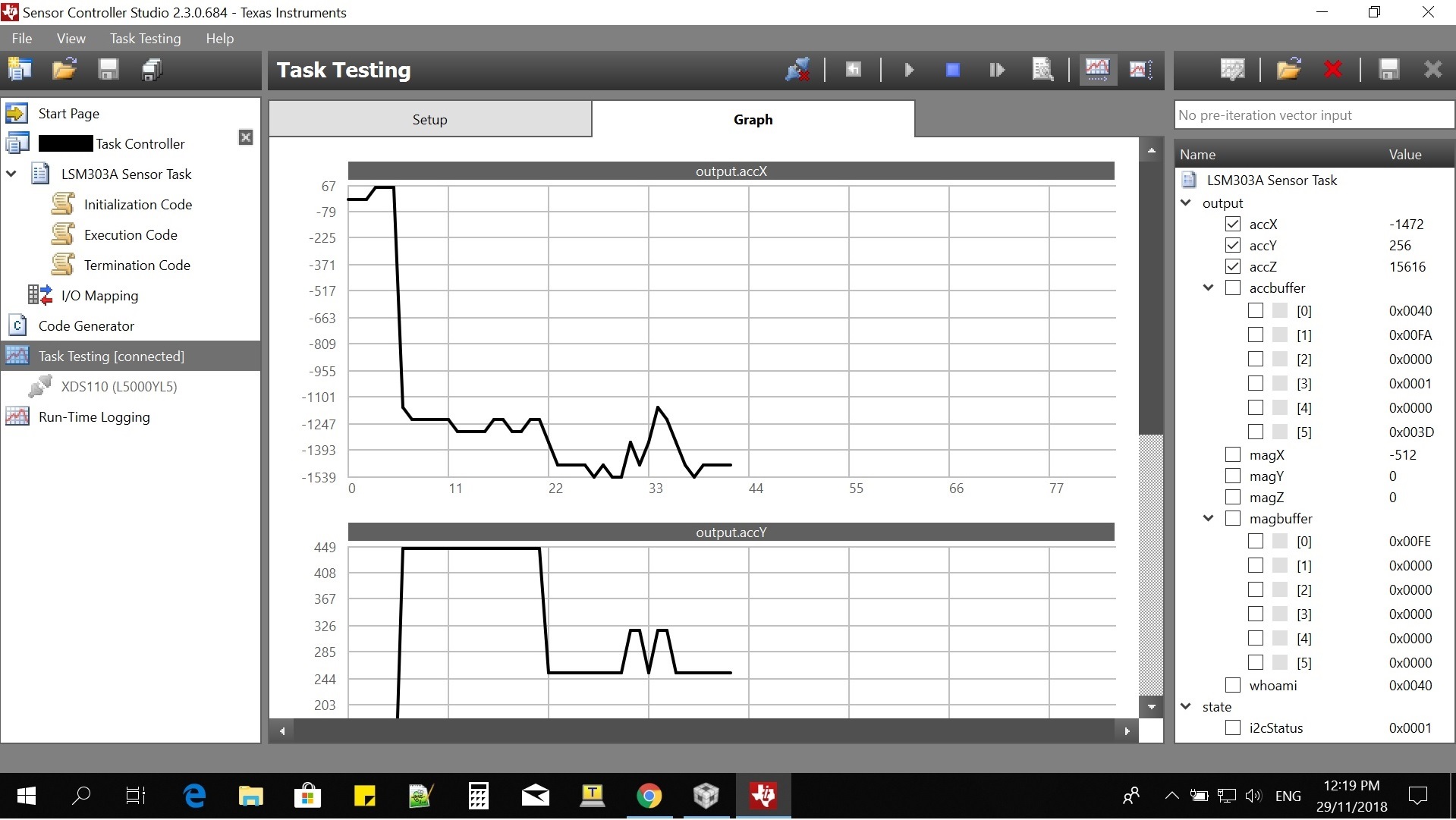
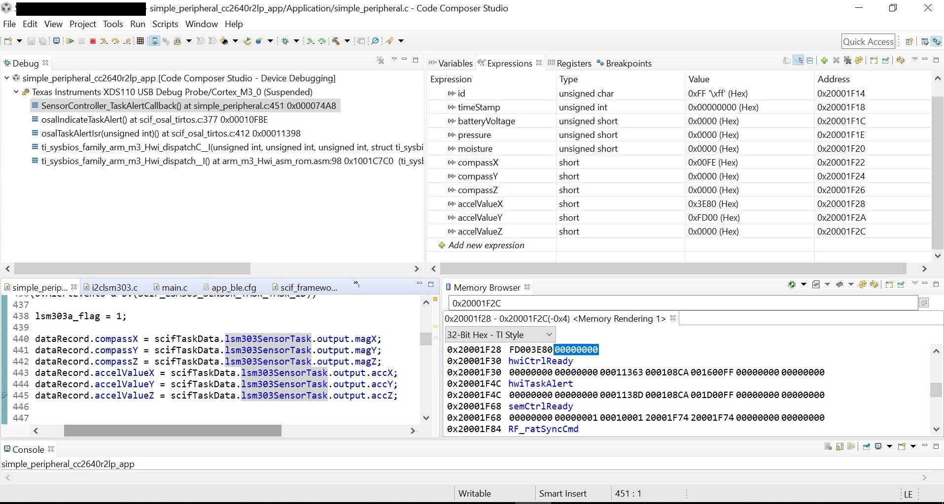
When I debug at CCS I am getting 0, see below. Why does that happen? I am passing the sensor controller data to a struct at main application.

-kel

  • Hi Markel,

    So it works when you are Task testing, does it also work when you do run-time logging?
  • Hi Edvard P,

    My custom board does not have UART output for run-time logging.

    -kel
  • Hi Edvard P,

    What is weird is it works at Task Testing numerous times, then I try to change the data type of one variable then return it back to original. Now it does not work.

    -kel
  • Hi Edvard P,

        I deleted some unnecessary code at Execution Code and now task testing works every time. This is my Bluetooth Service Log. I am executing the Sensor Controller Tasks every 10 seconds the last 12 bytes are Magnetometer X,Y,Z and Accelerometer X,Y,Z. highlighted in bold

    20:33:12.757 — Characteristic (F0001111-0451-4000-B000-000000000000) read: <aade77b9 00c90c04 00fa0bd2 fc000200 0080f900 000000>
    20:33:38.588 — Characteristic (F0001111-0451-4000-B000-000000000000) notified: <aaba77d7 00c90c04 00fa0b23 fd000200 08000000 000000>
    20:33:48.578 — Characteristic (F0001111-0451-4000-B000-000000000000) notified: <aab277e1 00c90c04 00fd0be7 fba00200 00c0cc40 000000>
    20:33:58.568 — Characteristic (F0001111-0451-4000-B000-000000000000) notified: <aab777eb 00c90c04 00e20b08 fc000200 00c00300 04003f>
    20:34:08.589 — Characteristic (F0001111-0451-4000-B000-000000000000) notified: <aa9977f5 00c90c04 00f90b03 fd000100 08000000 000000>
    20:34:18.578 — Characteristic (F0001111-0451-4000-B000-000000000000) notified: <aa8c77ff 00c90c03 00000c05 fd000100 08400000 000000>
    20:34:28.969 — Characteristic (F0001111-0451-4000-B000-000000000000) notified: <aa847709 01c90c04 00ef0b00 fc000000 00c0fbc0 dd0000>
    20:34:38.986 — Characteristic (F0001111-0451-4000-B000-000000000000) notified: <aa6b7713 01c90c04 00f60bf3 fcc20100 00400000 000000>
    20:34:48.977 — Characteristic (F0001111-0451-4000-B000-000000000000) notified: <aa6b771d 01c90c03 00fb0bf8 fafc0100 00000000 000000>
    20:34:58.966 — Characteristic (F0001111-0451-4000-B000-000000000000) notified: <aa6e7727 01c90c04 00e60b07 fd000000 07c02000 dd4000>
    20:35:08.957 — Characteristic (F0001111-0451-4000-B000-000000000000) notified: <aa477731 01c90c04 00f90b00 fd000000 00803600 e14000>
    20:35:18.977 — Characteristic (F0001111-0451-4000-B000-000000000000) notified: <aa72773b 01c90c04 00f10b23 fd8b0200 00c03900 ec0000>

    Why do I get all these zeroes at Magnetometer X,Y,Z and Accelerometer X,Y,Z? When I do Task Testing at Sensor Controller Studio there is always value at Accelerometer X, Y, Z as shown in the picture above.

    -kel

  • How are you retrieving data from the sensor, how much data, and how do you store it? Remember that the Sensor Controller only has 16-bit words, which means any other odd numbered data sizes must either be manually aligned either in the Sensor Controller or in the System CPU.
  • Hi Edvard P,

    Upon Bluetooth Connection I have a Periodic RTOS Clock Running every 10 seconds and calling these 3 functions below to start the Sensor Controller Task.

    static void SensorController_PressureSampler(void)
    {
        // Start the ADC Sampler task
        while (scifWaitOnNbl(0) != SCIF_SUCCESS);
        scifResetTaskStructs(BV(SCIF_PRESSURE_SENSOR_TASK_TASK_ID), BV(SCIF_STRUCT_OUTPUT));
        scifExecuteTasksOnceNbl(BV(SCIF_PRESSURE_SENSOR_TASK_TASK_ID));
    }
    
    static void SensorController_MoistureSampler(void)
    {
        // Start the ADC Sampler task
        while (scifWaitOnNbl(0) != SCIF_SUCCESS);
        scifResetTaskStructs(BV(SCIF_MOISTURE_SENSOR_TASK_TASK_ID), BV(SCIF_STRUCT_OUTPUT));
        scifExecuteTasksOnceNbl(BV(SCIF_MOISTURE_SENSOR_TASK_TASK_ID));
    }
    
    static void SensorController_LSM303AStartTask(void)
    {
        // Start the LSM303A task
        while (scifWaitOnNbl(0) != SCIF_SUCCESS);
        scifResetTaskStructs(BV(SCIF_LSM303A_SENSOR_TASK_TASK_ID), BV(SCIF_STRUCT_OUTPUT));
        scifExecuteTasksOnceNbl(BV(SCIF_LSM303A_SENSOR_TASK_TASK_ID));
    }

    Then I handle the Task Alert Callback below, and then send the data to my custom bluetooth service.

    void SensorController_TaskAlertCallback(void)
    {
        uint32_t bvAlertEvents = 0;
    
        // Clear the ALERT interrupt source
        scifClearAlertIntSource();
    
        // Get the alert events
        bvAlertEvents = scifGetAlertEvents();
    
        // If the ADC Pressure sampler task has finished ...
        if (bvAlertEvents & BV(SCIF_PRESSURE_SENSOR_TASK_TASK_ID))
        {
            pressure_flag = 1;
            dataRecord.pressure = scifTaskData.pressureSensorTask.output.pressureValue;
        }
    
        // If the ADC Moisture sampler task has finished ...
        if (bvAlertEvents & BV(SCIF_MOISTURE_SENSOR_TASK_TASK_ID))
        {
            moisture_flag = 1;
            dataRecord.moisture = scifTaskData.moistureSensorTask.output.moistureValue;
        }
    
        // If the LSM303A task has finished ...
    	if (bvAlertEvents & BV(SCIF_LSM303A_SENSOR_TASK_TASK_ID))
    	{
    		lsm303a_flag = 1;
    		dataRecord.compassX = scifTaskData.lsm303aSensorTask.output.magX;
    		dataRecord.compassY = scifTaskData.lsm303aSensorTask.output.magY;
    		dataRecord.compassZ = scifTaskData.lsm303aSensorTask.output.magZ;
    		dataRecord.accelValueX = scifTaskData.lsm303aSensorTask.output.accX;
    		dataRecord.accelValueY = scifTaskData.lsm303aSensorTask.output.accY;
    		dataRecord.accelValueZ = scifTaskData.lsm303aSensorTask.output.accZ;
    	}
    
        // Acknowledge the alert event
        scifAckAlertEvents();
    
        if((pressure_flag == 1)&&(moisture_flag == 1)&&(lsm303a_flag == 1))
        {
        	pressure_flag = 0;
        	moisture_flag = 0;
        	lsm303a_flag = 0;
    
            Event_post(syncEvent, SBP_SENSORS_DONE_EVT);
        }
    } // scTaskAlertCallback

    Overall I am collecting from Sensor Controller 16 bytes of sensor data. 

    At Sensor Controller my Data Structures output are as below. for LSM303A Task

    accX, accY, accZ, magX, magY, magZ - 16-bit signed decimal

    accbuffer[6], magbuffer[6] - 16-bit unsigned hexadecimal

    whoami - 16-bit unsigned hexadecimal

    output.magX = (output.magbuffer[1] | (output.magbuffer[0] << 8));
    output.magY = (output.magbuffer[3] | (output.magbuffer[2] << 8));
    output.magZ = (output.magbuffer[5] | (output.magbuffer[4] << 8));
    output.accX = ((output.accbuffer[1] << 8) | output.accbuffer[0]);
    output.accY = ((output.accbuffer[3] << 8) | output.accbuffer[2]);
    output.accZ = ((output.accbuffer[5] << 8) | output.accbuffer[4]);

    -kel

  • Are you sure you are receiving 8 bits of data at a time from the sensor?
  • Yes, you can see from my first post pic accbuffer[0-5]. I have tested this numerous times and there is no problem at the Sensor Controller Side. I have done a version where the LSM303AGR is read from main application RTOS and it has full data.

    I am using the internal oscillator 32.768kHz would this cause an issue?

    -kel
  • Hi,

        I thought the use of internal 32.768kHz RC Oscillator at our custom board is causing this issue. So I try with CC2640R2F Launchpad using external 32.768 kHz crystal + LSM303DLHC Board. Here is my Sensor Controller output. It clearly shows reading the accelerometer and magnetometer.

    Here is my Bluetooth Service log. It is still has lots of zeroes. 

    16:05:03.311 — Characteristic (F0001111-0451-4000-B000-000000000000) read: <aa58f401 003a0d06 008c01d4 fe000000 00c0ff00 000000>
    16:05:10.511 — Characteristic (F0001111-0451-4000-B000-000000000000) notified: <aa00f40b 003a0d09 008a01d4 fe000000 00000000 000000>
    16:05:20.502 — Characteristic (F0001111-0451-4000-B000-000000000000) notified: <aaf8f315 003a0d08 009101d4 fe000000 00400000 000000>
    16:05:30.492 — Characteristic (F0001111-0451-4000-B000-000000000000) notified: <aae6f31f 003a0d08 009501d4 fe000000 00400000 000000>
    16:05:40.513 — Characteristic (F0001111-0451-4000-B000-000000000000) notified: <aaf6f329 003a0d0d 009001d4 fe000000 00802000 2800d8>
    16:05:50.502 — Characteristic (F0001111-0451-4000-B000-000000000000) notified: <aae4f333 003a0d02 008501d4 fe000000 00c0c340 000000>
    16:06:00.493 — Characteristic (F0001111-0451-4000-B000-000000000000) notified: <aae4f33d 003a0d06 008f01d4 fe000000 00000000

    Why does this happen? I would like to also know why you do not have Sensor Controller example program that passes I2C Sensor Data to Main Application?

    Post edited . . .

    I am doing this below what is mentioned at "Getting Stated with  . . . . Sensor Controller " doc. But I am getting zeroes so I can not process the data.

    "Another use case for the Sensor Controller is to collect data and only wake the main processor for data processing. This use of the Sensor Controller offers two main benefits over using the main CPU exclusively. The first use being that since the Sensor Controller uses less power than the main CPU, the power used for collecting data is reduced significantly. When the Sensor Controller is done collecting data, it can generate an alert to wake the main CPU for processing the data"

    http://www.ti.com/lit/an/swra578/swra578.pdf

    -kel

  • How do you setup the BLE service and write new data?
  • Hi Edvard P.

    I have shared code from my previous post how I handle the Sensor Controller Task Alert. The BLE Service is Data Service from Project Zero.

    // Total 23 bytes
    typedef struct
    {
        uint8_t id; // ID to indicate the start of the data
        uint32_t timeStamp;
        uint16_t batteryVoltage;
        uint16_t pressure;
        uint16_t moisture;
        int16_t compassX;
        int16_t compassY;
        int16_t compassZ;
        int16_t accelValueX;
        int16_t accelValueY;
        int16_t accelValueZ;
    }__attribute__((packed)) DataRecord;
    
    static DataRecord dataRecord;
    
    void SensorController_TaskAlertCallback(void)
    {
        uint32_t bvAlertEvents = 0;
    
        // Clear the ALERT interrupt source
        scifClearAlertIntSource();
    
        // Get the alert events
        bvAlertEvents = scifGetAlertEvents();
    
        // If the ADC Pressure sampler task has finished ...
        if (bvAlertEvents & BV(SCIF_PRESSURE_SENSOR_TASK_TASK_ID))
        {
            pressure_flag = 1;
            dataRecord.pressure = scifTaskData.pressureSensorTask.output.pressureValue;
        }
    
        // If the ADC Moisture sampler task has finished ...
        if (bvAlertEvents & BV(SCIF_MOISTURE_SENSOR_TASK_TASK_ID))
        {
            moisture_flag = 1;
            dataRecord.moisture = scifTaskData.moistureSensorTask.output.moistureValue;
        }
    
        // If the LSM303A task has finished ...
    	if (bvAlertEvents & BV(SCIF_LSM303_SENSOR_TASK_TASK_ID))
    	{
    		lsm303a_flag = 1;
    		dataRecord.compassX = scifTaskData.lsm303SensorTask.output.magX;
    		dataRecord.compassY = scifTaskData.lsm303SensorTask.output.magY;
    		dataRecord.compassZ = scifTaskData.lsm303SensorTask.output.magZ;
    		dataRecord.accelValueX = scifTaskData.lsm303SensorTask.output.accX;
    		dataRecord.accelValueY = scifTaskData.lsm303SensorTask.output.accY;
    		dataRecord.accelValueZ = scifTaskData.lsm303SensorTask.output.accZ;
    	}
    
        // Acknowledge the alert event
        scifAckAlertEvents();
    
        if((pressure_flag == 1)&&(moisture_flag == 1)&&(lsm303a_flag == 1))
        {
        	pressure_flag = 0;
        	moisture_flag = 0;
        	lsm303a_flag = 0;
    
            Event_post(syncEvent, SBP_SENSORS_DONE_EVT);
        }
    }
    
    static void SimplePeripheral_taskFxn(UArg a0, UArg a1)
    {
     // . . . 
          if (events & SBP_SENSORS_DONE_EVT)
          {
    		SuramedPeripheral_processDataTransfer();
          }
    }
    
    static void SimplePeripheral_processDataTransfer(void)
    {
        dataRecord.id = 0xAA; //Set 0xAA to indicate start of sensor data
        dataRecord.timeStamp = Timestamp_get32();
        dataRecord.batteryVoltage = Batt_MeasureMV();
        memcpy(&es_DataVal[0], (uint8_t *)&dataRecord, sizeof(DataRecord));
    
        DataService_SetParameter(ES_DATA_ID, sizeof(DataRecord), &es_DataVal[0]);
    }


    -kel

  • Have you tried debugging the application and setting a breakpoint when you read the sensor controller data that you are actually reading meaningful data?
  • Hi Edvard P,

    Yes so many times. See, the picture I shared at my first posting. But I assume it is not meaningful data because I get zeroes.

    -kel
  • Could you show me how you configure and start the Sensor Controller tasks?
  • Edvard P. said:
    Could you show me how you configure and start the Sensor Controller tasks?

    I already replied that last November 29. 

    I implemented System_printf() at Main Application. here are the LSM303DLHC Accelerometer X, Y, Z that is read from Sensor Controller. Highlighted in bold are the normal Accelerometer readings. The Accelerometer X, Y, Z will always have a positive or negative value. If I read the LSM303DLHC Accelerometer X,Y,Z at Main Application RTOS, I will never get 0 values. 

    [Cortex_M3_0] accelo: x = 64, y = 0,z = 0
    accelo: x = 0, y = 0,z = 0
    accelo: x = -3200, y = 0,z = 0
    accelo: x = -11072, y = 64,z = 0
    accelo: x = 0, y = 0,z = 0
    accelo: x = 64, y = 0,z = 0
    accelo: x = -10112, y = 2176,z = 12032
    accelo: x = 64, y = 0,z = 0
    accelo: x = 1984, y = 9984,z = -14080
    accelo: x = -3648, y = 0,z = 0
    accelo: x = 0, y = 0,z = 0
    accelo: x = -4672, y = 0,z = 0
    accelo: x = 64, y = 0,z = 0
    accelo: x = -13440, y = 64,z = 0
    accelo: x = -13888, y = 0,z = 0
    accelo: x = 0, y = 0,z = 0
    accelo: x = -13888, y = 1984,z = -9216
    accelo: x = -13952, y = 0,z = 0
    accelo: x = -13952, y = 1664,z = -9216
    accelo: x = -13888, y = 1728,z = -9216
    accelo: x = -13952, y = 1664,z = -9216
    accelo: x = 64, y = 0,z = 0
    accelo: x = -13952, y = 0,z = 0
    accelo: x = -13952, y = 0,z = 0

    Can I get more help regarding this from TI Engineers who are involved with Sensor Controller development.

    -kel

  • I mean the initialization of the Sensor Controller interface. I can see SensorController_PressureSampler(), SensorController_MoistureSampler() and SensorController_LSM303AStartTask(), but they don't tell me much. I don't know in which contexts they are called. You aren't checking the return values of the scif*() functions either, which could potentially tell you more.
  • Hi Edvard P.

    I call the SensorController_Init() at SimplePeripheral_Init(), see below. I am reading Analog Pressure Sensor, Analog Moisture Sensor and I2C LSM303DLHC from Sensor Controller. The Analog Pressure Sensor and Analog Moisture Sensor I can pass the data to Main Application no problem. However the I2C LSM303DLHC I am getting zeroes, why is that?

    static void SensorController_Init(void)
    {
        // Initialize the Sensor Controller
        scifOsalInit();
        scifOsalRegisterCtrlReadyCallback(SensorController_ReadyCallback);
        scifOsalRegisterTaskAlertCallback(SensorController_TaskAlertCallback);
        scifInit(&scifDriverSetup);
     }
    
    
    static void SimplePeripheral_init(void)
    {
    // . . . 
    
      SensorController_Init();
    
    // . . .
    }
    

    -kel

  • Here is the LSM303 Task Execution code at Sensor Controller. 

    ///////////// Magnetometer
    
    
    do{
        i2cStart();
        // Set LSM303DLHC Magnetometer I2C Slave Address
        i2cTx((LSM303DLHC_MAG_I2C_ADDRESS << 1) | I2C_OP_WRITE);
        // Set to Continous Conversion (0x00)
        i2cTx(LSM303DLHC_MR_REG_M);
        i2cTx(0x00);
        i2cStop();
    }while(state.i2cStatus != 0x0000);
    
    do{
        i2cStart();
        // Set LSM303DLHC Magnetometer I2C Slave Address
        i2cTx((LSM303DLHC_MAG_I2C_ADDRESS << 1) | I2C_OP_WRITE);
        // Data output rate = 15Hz(0x10)
        i2cTx(LSM303DLHC_CRA_REG_M);
        i2cTx(0x10);
        i2cStop();
    }while(state.i2cStatus != 0x0000);
    
    do{
        i2cStart();
        // Set LSM303DLHC Magnetometer I2C Slave Address
        i2cTx((LSM303DLHC_MAG_I2C_ADDRESS << 1) | I2C_OP_WRITE);
        // Set gain = +/- 1.3g(0x20)
        i2cTx(LSM303DLHC_CRB_REG_M);
        i2cTx(0x20);
        i2cStop();
    }while(state.i2cStatus != 0x0000);
    
    // Read Magnetometer X, Y, Z
    i2cStart();
    i2cTx((LSM303DLHC_MAG_I2C_ADDRESS << 1) | I2C_OP_WRITE);
    i2cTx(LSM303DLHC_OUT_X_H_M);
    
    // If successful ...
    if (state.i2cStatus == 0x0000) {
        // Read the result
        i2cRepeatedStart();
        i2cTx((LSM303DLHC_MAG_I2C_ADDRESS << 1) | I2C_OP_READ);
        i2cRxAck(output.magbuff[0]);
        i2cStop();
    }
    
    i2cStart();
    i2cTx((LSM303DLHC_MAG_I2C_ADDRESS << 1) | I2C_OP_WRITE);
    i2cTx(LSM303DLHC_OUT_X_L_M);
    
    // If successful ...
    if (state.i2cStatus == 0x0000) {
        // Read the result
        i2cRepeatedStart();
        i2cTx((LSM303DLHC_MAG_I2C_ADDRESS << 1) | I2C_OP_READ);
        i2cRxAck(output.magbuff[1]);
        i2cStop();
    }
    
    i2cStart();
    i2cTx((LSM303DLHC_MAG_I2C_ADDRESS << 1) | I2C_OP_WRITE);
    i2cTx(LSM303DLHC_OUT_Y_H_M);
    
    // If successful ...
    if (state.i2cStatus == 0x0000) {
        // Read the result
        i2cRepeatedStart();
        i2cTx((LSM303DLHC_MAG_I2C_ADDRESS << 1) | I2C_OP_READ);
        i2cRxAck(output.magbuff[2]);
        i2cStop();
    }
    
    i2cStart();
    i2cTx((LSM303DLHC_MAG_I2C_ADDRESS << 1) | I2C_OP_WRITE);
    i2cTx(LSM303DLHC_OUT_Y_L_M);
    
    // If successful ...
    if (state.i2cStatus == 0x0000) {
        // Read the result
        i2cRepeatedStart();
        i2cTx((LSM303DLHC_MAG_I2C_ADDRESS << 1) | I2C_OP_READ);
        i2cRxAck(output.magbuff[3]);
        i2cStop();
    }
    
    i2cStart();
    i2cTx((LSM303DLHC_MAG_I2C_ADDRESS << 1) | I2C_OP_WRITE);
    i2cTx(LSM303DLHC_OUT_Z_H_M);
    
    // If successful ...
    if (state.i2cStatus == 0x0000) {
        // Read the result
        i2cRepeatedStart();
        i2cTx((LSM303DLHC_MAG_I2C_ADDRESS << 1) | I2C_OP_READ);
        i2cRxAck(output.magbuff[4]);
        i2cStop();
    }
    
    i2cStart();
    i2cTx((LSM303DLHC_MAG_I2C_ADDRESS << 1) | I2C_OP_WRITE);
    i2cTx(LSM303DLHC_OUT_Z_L_M);
    
    // If successful ...
    if (state.i2cStatus == 0x0000) {
        // Read the result
        i2cRepeatedStart();
        i2cTx((LSM303DLHC_MAG_I2C_ADDRESS << 1) | I2C_OP_READ);
        i2cRxAck(output.magbuff[5]);
        i2cStop();
    }
    
    output.magX = (output.magbuff[1] | (output.magbuff[0] << 8));
    output.magY = (output.magbuff[3] | (output.magbuff[2] << 8));
    output.magZ = (output.magbuff[5] | (output.magbuff[4] << 8));
    
    
    /// LSM303DLHC Accelerometer Init
    do{
        i2cStart();
        // Set LSM303AGR Accelerometer I2C Slave Address
        i2cTx((LSM303DLHC_ACC_I2C_ADDRESS << 1) | I2C_OP_WRITE);
        // X, Y and Z-axis enable, power on mode, o/p data rate 10 Hz(0x27)
        i2cTx(LSM303DLHC_CTRL_REG1_A);
        i2cTx(0x27);
        i2cStop();
    }while(state.i2cStatus != 0x0000);
    
    do{
        i2cStart();
        // Set LSM303AGR Accelerometer I2C Slave Address
        i2cTx((LSM303DLHC_ACC_I2C_ADDRESS << 1) | I2C_OP_WRITE);
        // Full scale +/- 2g, continuous update(0x00)
        i2cTx(LSM303DLHC_CTRL_REG4_A);
        i2cTx(0x00);
        i2cStop();
    }while(state.i2cStatus != 0x0000);
    
    // Read Accelerometer X, Y, Z
    i2cStart();
    i2cTx((LSM303DLHC_ACC_I2C_ADDRESS << 1) | I2C_OP_WRITE);
    i2cTx(LSM303DLHC_OUT_X_L_A);
    
    // If successful ...
    if (state.i2cStatus == 0x0000) {
        // Read the result
        i2cRepeatedStart();
        i2cTx((LSM303DLHC_ACC_I2C_ADDRESS << 1) | I2C_OP_READ);
        i2cRxAck(output.accbuff[0]);
        i2cStop();
    }
    
    i2cStart();
    i2cTx((LSM303DLHC_ACC_I2C_ADDRESS << 1) | I2C_OP_WRITE);
    i2cTx(LSM303DLHC_OUT_X_H_A);
    
    // If successful ...
    if (state.i2cStatus == 0x0000) {
        // Read the result
        i2cRepeatedStart();
        i2cTx((LSM303DLHC_ACC_I2C_ADDRESS << 1) | I2C_OP_READ);
        i2cRxAck(output.accbuff[1]);
        i2cStop();
    }
    
    i2cStart();
    i2cTx((LSM303DLHC_ACC_I2C_ADDRESS << 1) | I2C_OP_WRITE);
    i2cTx(LSM303DLHC_OUT_Y_L_A);
    
    // If successful ...
    if (state.i2cStatus == 0x0000) {
        // Read the result
        i2cRepeatedStart();
        i2cTx((LSM303DLHC_ACC_I2C_ADDRESS << 1) | I2C_OP_READ);
        i2cRxAck(output.accbuff[2]);
        i2cStop();
    }
    
    i2cStart();
    i2cTx((LSM303DLHC_ACC_I2C_ADDRESS << 1) | I2C_OP_WRITE);
    i2cTx(LSM303DLHC_OUT_Y_H_A);
    
    // If successful ...
    if (state.i2cStatus == 0x0000) {
        // Read the result
        i2cRepeatedStart();
        i2cTx((LSM303DLHC_ACC_I2C_ADDRESS << 1) | I2C_OP_READ);
        i2cRxAck(output.accbuff[3]);
        i2cStop();
    }
    
    i2cStart();
    i2cTx((LSM303DLHC_ACC_I2C_ADDRESS << 1) | I2C_OP_WRITE);
    i2cTx(LSM303DLHC_OUT_Z_L_A);
    
    // If successful ...
    if (state.i2cStatus == 0x0000) {
        // Read the result
        i2cRepeatedStart();
        i2cTx((LSM303DLHC_ACC_I2C_ADDRESS << 1) | I2C_OP_READ);
        i2cRxAck(output.accbuff[4]);
        i2cStop();
    }
    
    i2cStart();
    i2cTx((LSM303DLHC_ACC_I2C_ADDRESS << 1) | I2C_OP_WRITE);
    i2cTx(LSM303DLHC_OUT_Z_H_A);
    
    // If successful ...
    if (state.i2cStatus == 0x0000) {
        // Read the result
        i2cRepeatedStart();
        i2cTx((LSM303DLHC_ACC_I2C_ADDRESS << 1) | I2C_OP_READ);
        i2cRxAck(output.accbuff[5]);
        i2cStop();
    }
    
    output.accX = ((output.accbuff[1] << 8) | output.accbuff[0]);
    output.accY = ((output.accbuff[3] << 8) | output.accbuff[2]);
    output.accZ = ((output.accbuff[5] << 8) | output.accbuff[4]);
    
    // Signalize that the task has been completed
    fwGenAlertInterrupt();

  • Can you start a debug sessions and check the return values of scifResetTaskStructs() and scifExecuteTasksOnceNbl() when calling SensorController_LSM303AStartTask()?
  • Hi Severin,

    The scifResetTaskStructs() has no return. The scifExecuteTasksOnceNbl() returns SCIF_SUCCESS.

    -kel
  • I have BOOSTXL-SENSORS with several I2C sensors on it. If I read these I2C sensors the same way and I get zero values, there is a bug somewhere in Sensor Controller.

    -kel
  • Just some sanity checks, can you verify the sensor controller project has generated code, and that the SCIF files are the latest and greatest?

    Also, when reading the values from scifTaskData, could you verify in memory viewer that the corresponding address of the Sensor Controller memory actually reports 0?

  • It is the latest. I have been using Sensor Controller for a while now, so I am familiar with the code generation.

    Here shown at bottom right dataRecord.accelValueZ = scifTaskData.lsm303SensorTask.output.accZ; with memory address 0x20001F2C shows zero value.

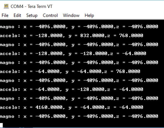
  • Here is Tera Term output when I read the LSM303DLHC board using TI-RTOS. There are no zero X,Y,Z.

    -kel

  • Hi Severin,

    I replaced the LSM303DLHC Board with OPT3001 at BOOSTXL-SENSORS. At Sensor Controller when the light lamp on my desk is on the OPT3001 reading is around 540 see, below.

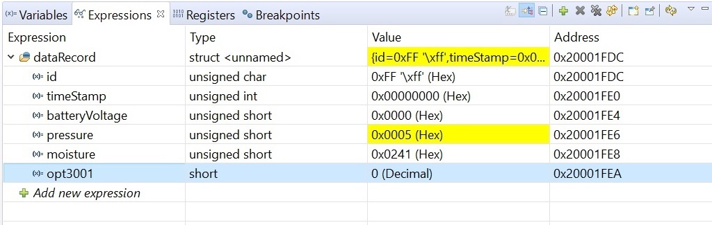
    At CCS I read 0, see below.

    If you want these CCS Project and Sensor Controller Code I can give it to you through PM. I will give you a link from which you can download it.

    I would like a confirmation from TI if this is really an issue or my code implementation is not right. If this is a Sensor Controller issue then we just use Main Application TI-RTOS to read I2C Sensor. But if that is so, this statement from your document is false claiming.

    "Another use case for the Sensor Controller is to collect data and only wake the main processor for data processing. This use of the Sensor Controller offers two main benefits over using the main CPU exclusively. The first use being that since the Sensor Controller uses less power than the main CPU, the power used for collecting data is reduced significantly. When the Sensor Controller is done collecting data, it can generate an alert to wake the main CPU for processing the data"

    http://www.ti.com/lit/an/swra578/swra578.pdf

    -kel

  • Yes please, if you could send me the code I could take a look at it.
  • Hi Severin,

    Temporarily my team decided to not use the Sensor Controller to read the I2C LSM303AGR Sensor. I re-used the CCS project that I was supposed to share to you, so I have nothing to share at the moment.

    But, there is still no conclusion to this, so I would like to keep this post open.

    From the many hours of debugging this here are my observations.

    1. Reading the I2C Accelerometer+Magnetometer Sensor using TI-RTOS main application always provide values. It never provides 0 value at either X,Y,Z
    2. Implementing the same code at Sensor Controller yields 0 values at either X,Y,Z. The cause of these 0 values from my observation is I2C error.

    I do not have I2C Logic Analyzer to show that 0 values are caused by I2C error. I have observed the same at the Sensor Controller OPT3001 example program.

    Meaning the I2C Sensor Controller performs poorly compared to using I2C TI-RTOS at Main Application. Can you verify this at TI side?

    -kel
  • I'm struggling to reproduce the issue without the necessary HW. I would really appreciate if you could provide a logic trace of the I2C pins in order to determine whether this is the I2C misbehaving or not. Would it be possible for you to at least send over the SCS project?
  • Hi Severin,

    I have sent you a friend request. I will share to you the SCS project and CCS Project through PM.

    -kel
  • Hi Severin,

    I tried to PM you but I get this message below.
    "Access Denied
    You don't have permission to access "e2e.ti.com/.../conversation on this server."
    -kel
  • Hi Severin,

    At "settings" set your Conversation Configuration to "Allow the following to start conversations with you - Friends"

    -kel

  • Ok, so I've taken a look at the code you sent, and have a couple of questions:

    * Do you use the I2C driver from the main application while the Sensor Controller task is also using the I2C?
    * If so, do you re-initialize the IO pins with the scifReinitIo() API before running the Sensor Controller task?
    * Also, would you please supply a logic trace of the I2C pins when the issue occurs.
  • Severin Suveren said:
    * Do you use the I2C driver from the main application while the Sensor Controller task is also using the I2C?
    * If so, do you re-initialize the IO pins with the scifReinitIo() API before running the Sensor Controller task?

    No.

    Severin Suveren said:
    * Also, would you please supply a logic trace of the I2C pins when the issue occurs.

    I do not have logic analyzer at the moment.

    -kel

  • Are you sure? When I take a look at the project you sent me, it seems like you are using the I2C driver.

    In order to determine that the issue is with the I2C, I definitely need a logic trace of the pins.
  • Hi,

    The simple peripheral stack library CCS project I shared to you which integrates the Sensor Controller does not use I2C at main application. I do not have logic analyzer to capture the I2C signal.

    I debugged this and is really pointing to the I2C of Sensor Controller performs poorly compared to I2C of TI-RTOS Main Application. Even the OPT3001 Sensor Controller Example Program does not always give an output. I need to modify the Sensor Controller code to make it always give an output. 

    I assume since you are in TI you have all the I2C sensor board  and test equipment to confirm this. If not maybe another TI Engineer can.

    -kel

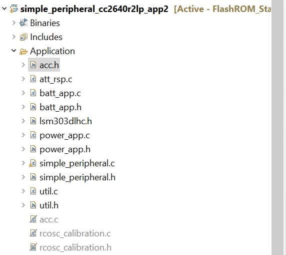
  • But the simple_peripheral_cc2640r2lp_app2 project does interface the I2C driver... I'm strictly referring to Application/acc.c.

    We are unable to reproduce the issue you are facing. To me it sounds like the I2C pins aren't properly initialized or re-initialized by the main application before the Sensor Controller task is using I2C. This causes the I2C communication to fail on the SC task, which in turn provides garbage data to the main application.

    I need a logic trace in order to verify that this is the case.
  • Severin Suveren said:
    But the simple_peripheral_cc2640r2lp_app2 project does interface the I2C driver... I'm strictly referring to Application/acc.c.

    We are unable to reproduce the issue you are facing. To me it sounds like the I2C pins aren't properly initialized or re-initialized by the main application before the Sensor Controller task is using I2C. This causes the I2C communication to fail on the SC task, which in turn provides garbage data to the main application.

    No you arrive at a wrong conclusion. You were not able to reproduce my problem because you do not have a CC2640R2F LP and BOOSTXL-SENSORS setup, am I right?. The acc.c is not part of the build. The CCS project I shared to you is for my testing so there are extra files.

    -kel

  • Ok, thanks for clarifying regarding acc.c.

    I do have the necessary HW, both a LAUNCHXL-CC2640R2 and a BOOSTXL-SENSORS. I am not able to reproduce the issue with the SW you provided. I compiled the simple_peripheral project, no modifications, and flashed the LP. I had no problem reading the values from the Sensor Controller task after I formed a BLE connection with the device. See attached picture.

  • Hi Severin,

    Thanks for the effort. There is no problem with the I2C OPT3001. But, it is different story when reading I2C LSM303 using Sensor Controller as I have shared the details. I will mark this post as resolved and just create a new one if I have further questions.

    -kel
  • If you ever get a logic trace of the I2C pins, let me know.