This thread has been locked.

If you have a related question, please click the "Ask a related question" button in the top right corner. The newly created question will be automatically linked to this question.

CCS/LAUNCHXL-CC2640R2: Can't Read ID from External Flash (IS25LP256D)

Part Number: LAUNCHXL-CC2640R2
Other Parts Discussed in Thread: CC2640R2F, CC2640

Tool/software: Code Composer Studio

Hi,

I am  trying to interface an external flash with CC2640R2 MCU. The part number for flash is IS25LP256D. In the datasheet of flash it is mentioned as the device is able to work in SPI mode 0 ( spiParams.frameFormat = SPI_POL0_PHA0 ) and SPI mode 3( spiParams.frameFormat = SPI_POL1_PHA1 ).

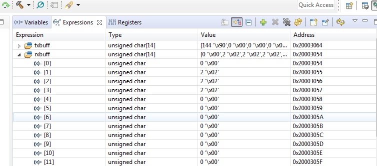
I am trying to find the ID of flash device for that I am sending an instruction '0x90' through the txbuff.

But, In Mode 0, There is not output at all.

In the case of Mode 3, I am getting a value '2' in the rxbuff of SPI.

But, as mentioned in datasheet of Flash, I was supposed to get '18' in the rxbuff.

I am confused whether I am getting the exact result or some error value. 

Please help..!!!!

  • Dear Gokul H,


    Do you have a logic logic analyzers that you can use to probe the SPI signals? If so, can you post your trace here?

    With the 0x90 instruction you are supposed to get 2 ID bytes back (Manufacturer and device), are you only reading one byte back? What address are you setting (A0)?

    Best Regards,
    R.M
  • Hi,

    This  is the function that I used.

    /*!< Send "RDID " instruction */

     txbuff[0] = issiFLASH_CMD_RDPID;

     txbuff[1] = issiFLASH_DUMMY_BYTE;

     txbuff[2] = issiFLASH_DUMMY_BYTE;

     txbuff[3] = issiFLASH_DUMMY_BYTE;

     Send_spi(txbuff,rxbuff,4);

    /*The instruction is defined as follows:*/

    #define issiFLASH_CMD_RDPID             0x90//AB  /*!< Read product identification */

    As per the datasheet, I have sent 0xAB but no data was available in rxbuff. The i tried with 0x90 and got the value '2'.

    Since, I am sending 3 dummy cycles I got same value thrice.

    The SPI initialization code as follows

    void spi_init()
    {
    //PIN_init(BoardGpioInitTable);

    /* Open LED pins */
    pinHandle = PIN_open(&pinState, spipinTable);
    if(!pinHandle) {
    System_abort("Error initializing board pins\n");
    }
    spiParams.mode = SPI_MASTER;
    spiParams.dataSize = 8;
    spiParams.transferMode = SPI_MODE_BLOCKING;
    spiParams.transferTimeout = SPI_WAIT_FOREVER;
    spiParams.bitRate = 12000000;
    spiParams.custom =(uintptr_t) NULL;
    spiParams.frameFormat = SPI_POL1_PHA1;
    spiParams.transferCallbackFxn = NULL;
    //SPI_Params_init(&spiParams); // Initialize SPI parameters
    // 8-bit data size
    SPI_init(); // Initialize the SPI driver
    spi = SPI_open(Board_SPI0, &spiParams);
    if (spi == NULL)
    System_abort("Error initializing spi\n"); // SP

    printf("spi initialised\n");
    }

    I dont have a logic analyzer with me. But i checked the MOSI and CS lines using DSO.

  • Dear Gokul H,

    I see that you use 12 MHz as bit rate, can you reduce that and see if it helps?
    Maximum supported bit rate for Master and duplex operation for CC2640R2F is 6 MHz (8 system clocks)

    Best Regards,
    R.M
  • Hi,

    I haven’t heard from you for two weeks, so I’m assuming you were able to resolve your issue. If this isn’t the case, please click the "This did NOT resolve my issue" button and reply to this thread with more information. If this thread locks, please click the "Ask a related question" button and in the new thread describe the current status of your issue and any additional details you may have to assist us in helping to solve your issues.

    Regards,
    R.M
  • hello,
    I reduced the bit rate to 6Mhz Then also the result is the same
  • should i use SPI_FLASH_CS config for communicating to flash or NORMAL SPI0/SPI1 config.
  • Also there is one more issue to be resolved regarding dual spi in cc2640.
    Please provide sample code that demonstrates the use of spi0 and spi1 .
    In our application spi0 is used to communicate with CAN driver and spi1 to flash memory.But as stated above communication with flash is not taking place, so for testing purpose of dual spi communication with spi of arduino is checked. But that also is not working
    Please provide any documents to help me with the problem
  • Hi,

    Have you tried reducing the speed lower than 6 MHz? I would try with <1 MHz just to see if speed is the issue.
    I strongly recommend that you get a hold of a logic analyzer and probe the signals so that we can debug further.

    We do not have sample code for dual SPI usage.

    Best Regards,
    R.M
  • Hi,

    I haven’t heard from you for several weeks, so I’m assuming you were able to resolve your issue. If this isn’t the case, please click the "This did NOT resolve my issue" button and reply to this thread with more information. If this thread locks, please click the "Ask a related question" button and in the new thread describe the current status of your issue and any additional details you may have to assist us in helping to solve your issues.

    Regards,
    R.M