This thread has been locked.

If you have a related question, please click the "Ask a related question" button in the top right corner. The newly created question will be automatically linked to this question.

RTOS/CC2640R2F: Example for continuous receiving data from a UART peripheral

Part Number: CC2640R2F
Other Parts Discussed in Thread: CC1310, , CC2640

Tool/software: TI-RTOS

Hello,

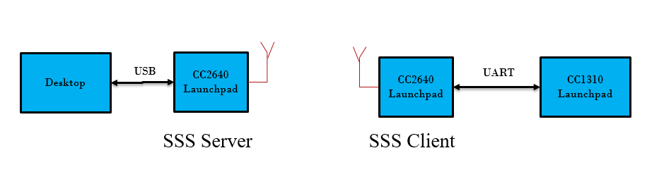
I'm working on CC2640R2F Launchpad. I would like to use another CC1310 to continuously sending some data packet to it through UART and send out all the data through Bluetooth. Is there any example I could follow to implement continuous UART receicving? Is it better to use TI-RTOS driver or your NPI?

Thank you so much! 

  • Hey Jianlin,

    We have a project that does what you are asking on our Github here: github.com/.../simplelink_cc2640r2_sdk-2.20

    Please let me know if you have any follow up questions!
  • Hello Ammar,

    Thank you for your quick reply. I have tested your SSS code and ran your server and client demo which worked well with two launchpads connected to desktop with USB. However, if I disable the client board USB and connect its UART port DIO2 and DIO3 to another device(cc1310) which is coninuous sending a 804 Bytes data packet to the CC2640 device(client), I could not see any data received at my SSS server. Baudrate are all set to 115200.

    My set-up is like following:


    And my hardware connection is:

    I also have did the modification for large data transfers according to your Git doc.

    1. Is your demo only works for UART using emulator and USB?  If not, is there any special setting I should modified to make it work?

    2. Is it possible to connect two devices to CC2640 based on this SSS demo?

    Thank you so much! 

  • Hey Jianlin,

    Thank you for the picture! I noticed that you still have the TX/RX jumpers connected.

    You'll have to remove those jumpers so that you can use the header pins below as TX/RX. This will disable the ability to use USB, but enable you to send your custom packets via the BLE bridge.

    As a quick test (only TX was tested), here's what I've done:
    1) Loaded the CC1310 with a modified uartecho to only transmit 'A's forever (in your case load the uart code)
    2) Load one CC2640R2 with the spp_client code
    3) Remove TX/RX jumpers from both the CC2640R2 and the CC1310.
    4) Using a jumper cable, connect DIO3 to DIO3 on both boards.
    5) The CC2640R2 running the spp_server code should be receiving 'A's via BLE.
  • Hi Ammar,

    Thanks for your reply. It works when I remove the RXD and TXD head jumpers. Could you please tell me why it won't work with them on? I tested with oscilloscope and could see signal on my DIO2 pin.


    Thanks a lot!
  • Having two devices connected to one serial communication line can lead to bus contention. From a hardware perspective, you cannot have two devices trying to transmit on the same line. If one device sends a 0, and the other sends a 1, then you can short the device. For that reason, you can only have one device connected (usually).

    For similar reasons, you cannot open two Putty terminals on the same port, because two devices cannot open the serial port at the same time.
  • Dear Ammar,

    Could you please take a look at my question in the following post?

    I got some packet drop issue when I was using your example. Is it something you suspect or cause by my wrong modification?

    Thanks a lot!

  • Sure. Please look there for a follow-up response.