This thread has been locked.

If you have a related question, please click the "Ask a related question" button in the top right corner. The newly created question will be automatically linked to this question.

CCS/CC2640R2F: Program crashed when turn off the optimization

Part Number: CC2640R2F

Tool/software: Code Composer Studio

Hi

I have been working on CC2640R2f LP based on simple_peripheral example, and my SDK version is simplelink_cc2640r2_sdk_2_30_00_28.

I have been trying to make the BLE Stack, DMA and PWM work together, but I found out that for some reason I cannot reconnect to the peripheral after uDMAChannelTransferSet and at that time timers haven't be set yet.

After some experiments, I noticed that if I set optimization level to 4 ,the program can work properly. What I am curious about  is that I have tried modifying task stack size and C system stack size before, and it changed nothing. So I would like to ask that what else need to do to make my program work with optimization off.

Wish all help

Alex

  • Hi,
    Is there a specific reason that you do not wish to use optimization?
  • Hi

    Thanks for reply.

    Because the program is  still in early development , and I am really new to Ti stuff, so I think it would be easier to debug with optimization off. Also, I am a little worried about the stability of my program and I am trying to figure out the specific reason that caused BLE Stack works improperly.

    Alex

  • Hi Alex,

    In addition to looking at the task stacks, you can look at the ICall heap when this happens. Link:

    Did you try pausing the debug session to see if the application has run into an exception?

    BTW, here is a small example of how to use DMA with PWM:

    /*
     * Copyright (c) 2015-2017, Texas Instruments Incorporated
     * All rights reserved.
     *
     * Redistribution and use in source and binary forms, with or without
     * modification, are permitted provided that the following conditions
     * are met:
     *
     * *  Redistributions of source code must retain the above copyright
     *    notice, this list of conditions and the following disclaimer.
     *
     * *  Redistributions in binary form must reproduce the above copyright
     *    notice, this list of conditions and the following disclaimer in the
     *    documentation and/or other materials provided with the distribution.
     *
     * *  Neither the name of Texas Instruments Incorporated nor the names of
     *    its contributors may be used to endorse or promote products derived
     *    from this software without specific prior written permission.
     *
     * THIS SOFTWARE IS PROVIDED BY THE COPYRIGHT HOLDERS AND CONTRIBUTORS "AS IS"
     * AND ANY EXPRESS OR IMPLIED WARRANTIES, INCLUDING, BUT NOT LIMITED TO,
     * THE IMPLIED WARRANTIES OF MERCHANTABILITY AND FITNESS FOR A PARTICULAR
     * PURPOSE ARE DISCLAIMED. IN NO EVENT SHALL THE COPYRIGHT OWNER OR
     * CONTRIBUTORS BE LIABLE FOR ANY DIRECT, INDIRECT, INCIDENTAL, SPECIAL,
     * EXEMPLARY, OR CONSEQUENTIAL DAMAGES (INCLUDING, BUT NOT LIMITED TO,
     * PROCUREMENT OF SUBSTITUTE GOODS OR SERVICES; LOSS OF USE, DATA, OR PROFITS;
     * OR BUSINESS INTERRUPTION) HOWEVER CAUSED AND ON ANY THEORY OF LIABILITY,
     * WHETHER IN CONTRACT, STRICT LIABILITY, OR TORT (INCLUDING NEGLIGENCE OR
     * OTHERWISE) ARISING IN ANY WAY OUT OF THE USE OF THIS SOFTWARE,
     * EVEN IF ADVISED OF THE POSSIBILITY OF SUCH DAMAGE.
     */
    
    /*
     *  ======== empty.c ========
     */
    
    /* For usleep() */
    #include <unistd.h>
    #include <stdint.h>
    #include <stddef.h>
    
    /* Driver Header files */
    #include <ti/drivers/GPIO.h>
    #include <ti/drivers/PWM.h>
    #include <ti/drivers/timer/GPTimerCC26XX.h>
    #include <ti/drivers/Power.h>
    
    // #include <ti/drivers/UART.h>
    // #include <ti/drivers/Watchdog.h>
    
    #include <ti/drivers/dma/UDMACC26XX.h>
    
    #include <ti/devices/DeviceFamily.h>
    #include DeviceFamily_constructPath(inc/hw_memmap.h)
    #include DeviceFamily_constructPath(inc/hw_gpt.h)
    #include DeviceFamily_constructPath(inc/hw_event.h)
    #include DeviceFamily_constructPath(driverlib/udma.h)
    
    /* Allocate the DMA software 0 table */
    ALLOCATE_CONTROL_TABLE_ENTRY(dmaSoftwareDmaPri, UDMA_CHAN_SW_EVT0);
    ALLOCATE_CONTROL_TABLE_ENTRY(dmaSoftwareDmaAlt, (UDMA_CHAN_SW_EVT0 + UDMA_ALT_SELECT));
    
    /* Allocate the DMA GPTimerA1 tables */
    ALLOCATE_CONTROL_TABLE_ENTRY(dmaTimerDmaPri, (UDMA_CHAN_TIMER1_A + UDMA_PRI_SELECT));
    ALLOCATE_CONTROL_TABLE_ENTRY(dmaTimerDmaAlt, (UDMA_CHAN_TIMER1_A + UDMA_ALT_SELECT));
    
    /* Board Header file */
    #include "Board.h"
    
    /* Shared global variables */
    UDMACC26XX_Handle dmaHandle;
    static uint8_t counter = 0;
    static uint8_t reloadCounter = 0;
    
    /* ================== Used in step (1) ================== */
    uint16_t mySoftwareTable[5] = {1, 2, 3, 4, 5};
    
    /* ================== Used in step (2) and (3) ================== */
    /* Note that no value is larger then the max 16-bit value, this means we don't need to handle the pre-scaler using the DMA */
    uint16_t myPwmDutyInCounts[5] = {
                                        /* For 1000 Hz */
                                        4800,    /* 10% duty */
                                        9600,    /* 20% duty */
                                        14400,   /* 30% duty */
                                        19200,   /* 40% duty */
                                        24000,   /* 50% duty */
                                    };
    
    void timerCallback(GPTimerCC26XX_Handle handle, GPTimerCC26XX_IntMask interruptMask) {
        /* We need to re-load the previous DMA table for the ping-pong to work.
         * As every table takes 5 timer interrupts to complete, we only reset
         * every fifth interrupt we get. */
        counter++;
        reloadCounter++;
        if ((reloadCounter == 4) && (counter < 30)) {
            reloadCounter = 0;
            /* If currently on the "Alternative table", we reload the primary */
            uint32_t resetControl = UDMA_MODE_PINGPONG |                       // Basic Ping-Pong
                                    UDMA_SIZE_16 |                             // 16-bit transfers
                                    UDMA_SRC_INC_16 |                          // Increment source address as 16-bit
                                    UDMA_DST_INC_NONE |                        // Do not increment destination address
                                    UDMA_ARB_1 |                               // Arbitrate system bus for 1 transfer at a time
                                    UDMACC26XX_SET_TRANSFER_SIZE(5);           // Setup number of transfers (in frames of 16-bit)
    
            if (HWREG(UDMA0_BASE + UDMA_O_SETCHNLPRIALT) & (1 << UDMA_CHAN_TIMER1_A)) {
                dmaTimerDmaPri.ui32Control = resetControl;
                dmaTimerDmaPri.pvSrcEndAddr = (void *) (myPwmDutyInCounts + 4);         // Set source end address (mind the pointer arithmetic)
                dmaTimerDmaPri.pvDstEndAddr = (void *) (GPT0_BASE + GPT_O_TAMATCHR);    // Set destination end address to GPTimerA0 match register
    
            }
            else {
                dmaTimerDmaAlt.ui32Control = resetControl;
                dmaTimerDmaAlt.pvSrcEndAddr = (void *) (myPwmDutyInCounts + 4);         // Set source end address (mind the pointer arithmetic)
                dmaTimerDmaAlt.pvDstEndAddr = (void *) (GPT0_BASE + GPT_O_TAMATCHR);    // Set destination end address to GPTimerA0 match register
            }
        }
    }
    
    /* ================== Used in step (4) ================== */
    uint32_t myPwmPeriodInCountsScatter[25] = {
                                         48000,     /* 1000 Hz */
                                         48000,     /* 1000 Hz */
                                         48000,     /* 1000 Hz */
                                         48000,     /* 1000 Hz */
                                         48000,     /* 1000 Hz */
                                         4800,      /* 10000 Hz */
                                         4800,      /* 10000 Hz */
                                         4800,      /* 10000 Hz */
                                         4800,      /* 10000 Hz */
                                         4800,      /* 10000 Hz */
                                         960,       /* 50000 Hz */
                                         960,       /* 50000 Hz */
                                         960,       /* 50000 Hz */
                                         960,       /* 50000 Hz */
                                         960,       /* 50000 Hz */
                                         600,       /* 80000 Hz */
                                         600,       /* 80000 Hz */
                                         600,       /* 80000 Hz */
                                         600,       /* 80000 Hz */
                                         600,       /* 80000 Hz */
                                         480,       /* 100000 Hz */
                                         480,       /* 100000 Hz */
                                         480,       /* 100000 Hz */
                                         480,       /* 100000 Hz */
                                         480,       /* 100000 Hz */
                                    };
    
    /* Note that no value is larger then the max 16-bit value, this means we don't need to handle the pre-scaler using the DMA */
    uint16_t myPwmDutyInCountsScatter[25] = {
                                        /* For 1000 Hz */
                                        4800,    /* 10% duty */
                                        9600,    /* 20% duty */
                                        14400,   /* 30% duty */
                                        19200,   /* 40% duty */
                                        24000,   /* 50% duty */
                                        /* For 10000 Hz */
                                        480,    /* 10% duty */
                                        960,    /* 20% duty */
                                        1440,   /* 30% duty */
                                        1920,   /* 40% duty */
                                        2400,   /* 50% duty */
                                        /* For 50000 Hz */
                                        96,    /* 10% duty */
                                        192,   /* 20% duty */
                                        288,   /* 30% duty */
                                        384,   /* 40% duty */
                                        480,   /* 50% duty */
                                        /* For 80000 Hz */
                                        60,    /* 10% duty */
                                        120,   /* 20% duty */
                                        180,   /* 30% duty */
                                        240,   /* 40% duty */
                                        300,   /* 50% duty */
                                        /* For 100000 Hz */
                                        48,    /* 10% duty */
                                        96,    /* 20% duty */
                                        144,   /* 30% duty */
                                        192,   /* 40% duty */
                                        240,   /* 50% duty */
                                    };
    
    /* DMA Control tables */
    tDMAControlTable MyTaskList[3];
    tDMAControlTable updatePeriodTask;
    tDMAControlTable updateDutyTask;
    
    void timerCallbackMemoryScatter(GPTimerCC26XX_Handle handle, GPTimerCC26XX_IntMask interruptMask) {
    
        if (counter < 24) {
            while(uDMAGetStatus(UDMA0_BASE) & 0xF0);
            /* Update the period and duty task source pointers to traverse the array */
            MyTaskList[0].pvSrcEndAddr = (void *) (((uint32_t *)MyTaskList[0].pvSrcEndAddr) + 1);
            MyTaskList[1].pvSrcEndAddr = (void *) (((uint16_t *)MyTaskList[1].pvSrcEndAddr) + 1);
    
            /* Once the scatter-gather completes, the channel is disabled. We need to re-arm the transfer again */
            uDMAChannelScatterGatherSet(UDMA0_BASE, UDMA_CHAN_TIMER1_A, 3, MyTaskList, UDMA_MODE_PER_SCATTER_GATHER);
            UDMACC26XX_channelEnable(dmaHandle, 1 << UDMA_CHAN_TIMER1_A);
        }
    
        counter++;
    }
    /*
     *  ======== mainThread ========
     */
    void *mainThread(void *arg0)
    {
        /* Call driver init functions */
        PWM_init();
    
        /* Open the uDMA driver */
        dmaHandle = UDMACC26XX_open();
        while(!dmaHandle){};
    
        /* Initialize the PWM parameters */
        PWM_Params pwmParams;
        PWM_Params_init(&pwmParams);
        pwmParams.idleLevel = PWM_IDLE_LOW;         /* Output low when PWM is not running */
        pwmParams.periodUnits = PWM_PERIOD_COUNTS;  /* Period is in counts */
        pwmParams.periodValue = 1;                  /* 0 MHz period (for now) */
        pwmParams.dutyUnits = PWM_DUTY_COUNTS;      /* Duty is in counts */
        pwmParams.dutyValue = 0;                    /* 0% initial duty cycle */
    
        /* Open PWM driver, Board_PWM0 (note that this typically use GPTimerA0) */
        PWM_Handle pwm = PWM_open(Board_PWM0, &pwmParams);
        while(!pwm){};
    
        /* Open GPTimer driver */
        GPTimerCC26XX_Params params;
        GPTimerCC26XX_Params_init(&params);
        params.width          = GPT_CONFIG_32BIT;
        params.mode           = GPT_MODE_PERIODIC_UP;
        params.debugStallMode = GPTimerCC26XX_DEBUG_STALL_OFF;
        GPTimerCC26XX_Handle hTimer = GPTimerCC26XX_open(Board_GPTIMER1A, &params);
        while(!hTimer){};
    
        /* 1. ================= Software triggered DMA from table to single variable ================= */
    
        /* Dummy variable to write to */
        uint16_t dummy = 0;
    
        /* Setup DMA transfer table */
        dmaSoftwareDmaPri.ui32Control =  UDMA_MODE_BASIC |                                                             // Basic mode
                                         UDMA_SIZE_16 |                                                                // 16-bit transfers
                                         UDMA_SRC_INC_16 |                                                             // Increment source address as 16-bit
                                         UDMA_DST_INC_NONE |                                                           // Do not increment destination address
                                         UDMA_ARB_1 |                                                                  // Arbitrate system bus for 1 transfer at a time
                                         UDMACC26XX_SET_TRANSFER_SIZE(sizeof(mySoftwareTable) / sizeof(uint16_t));     // Setup number of transfers (in frames of 16-bit)
        dmaSoftwareDmaPri.pvSrcEndAddr = (void *)(mySoftwareTable + (sizeof(mySoftwareTable) / sizeof(uint16_t)) - 1); // Set source end address (mind the pointer arithmetic)
        dmaSoftwareDmaPri.pvDstEndAddr = &dummy;                                                                       // Set destination end address
    
        /* Enable DMA software channel 0 */
        UDMACC26XX_channelEnable(dmaHandle, 1 << UDMA_CHAN_SW_EVT0);
    
        /* Trigger SW DMA transfer event */
        uDMAChannelRequest(UDMA0_BASE, UDMA_CHAN_SW_EVT0);
        while(uDMAGetStatus(UDMA0_BASE) & 0xF0);
        /* Dummy is now 1 */
        uDMAChannelRequest(UDMA0_BASE, UDMA_CHAN_SW_EVT0);
        while(uDMAGetStatus(UDMA0_BASE) & 0xF0);
        /* Dummy is now 2 */
        uDMAChannelRequest(UDMA0_BASE, UDMA_CHAN_SW_EVT0);
        while(uDMAGetStatus(UDMA0_BASE) & 0xF0);
        /* Dummy is now 3 */
        uDMAChannelRequest(UDMA0_BASE, UDMA_CHAN_SW_EVT0);
        while(uDMAGetStatus(UDMA0_BASE) & 0xF0);
        /* Dummy is now 4 */
        uDMAChannelRequest(UDMA0_BASE, UDMA_CHAN_SW_EVT0);
        while(uDMAGetStatus(UDMA0_BASE) & 0xF0);
        /* Dummy is now 5 */
    
        /* Disable DMA software channel 0 */
        UDMACC26XX_channelDisable(dmaHandle, 1 << UDMA_CHAN_SW_EVT0);
    
        /* =================  2. Update PWM duty using SW triggered DMA ================= */
    
        /* Setup DMA transfer table */
        dmaSoftwareDmaPri.ui32Control =  UDMA_MODE_BASIC |                      // Basic mode
                                         UDMA_SIZE_16 |                         // 16-bit transfers
                                         UDMA_SRC_INC_16 |                      // Increment source address as 16-bit
                                         UDMA_DST_INC_NONE |                    // Do not increment destination address
                                         UDMA_ARB_1 |                           // Arbitrate system bus for 1 transfer at a time
                                         UDMACC26XX_SET_TRANSFER_SIZE(5);       // Setup number of transfers (in frames of 16-bit)
    
        dmaSoftwareDmaPri.pvSrcEndAddr = (void *) (myPwmDutyInCounts + 4);      // Set source end address (mind the pointer arithmetic)
        dmaSoftwareDmaPri.pvDstEndAddr = (void *) (GPT0_BASE + GPT_O_TAMATCHR); // Set destination end address to GPTimerA0 match register
    
        /* Use 1000 Hz as period */
        PWM_setPeriod(pwm, 48000);
        PWM_start(pwm);
    
        /* Enable DMA software channel 0 */
        UDMACC26XX_channelEnable(dmaHandle, 1 << UDMA_CHAN_SW_EVT0);
    
        /* Trigger SW DMA transfer event */
        uDMAChannelRequest(UDMA0_BASE, UDMA_CHAN_SW_EVT0);
        while(uDMAGetStatus(UDMA0_BASE) & 0xF0);
        /* Duty is now 10% */
        uDMAChannelRequest(UDMA0_BASE, UDMA_CHAN_SW_EVT0);
        while(uDMAGetStatus(UDMA0_BASE) & 0xF0);
        /* Duty is now 20% */
        uDMAChannelRequest(UDMA0_BASE, UDMA_CHAN_SW_EVT0);
        while(uDMAGetStatus(UDMA0_BASE) & 0xF0);
        /* Duty is now 30% */
        uDMAChannelRequest(UDMA0_BASE, UDMA_CHAN_SW_EVT0);
        while(uDMAGetStatus(UDMA0_BASE) & 0xF0);
        /* Duty is now 40% */
        uDMAChannelRequest(UDMA0_BASE, UDMA_CHAN_SW_EVT0);
        while(uDMAGetStatus(UDMA0_BASE) & 0xF0);
        /* Duty is now 50% */
    
        /* Disable DMA software channel 0 */
        UDMACC26XX_channelDisable(dmaHandle, 1 << UDMA_CHAN_SW_EVT0);
    
        /* Disable PWM */
        PWM_stop(pwm);
    
        /* ================= 3. Update duty on Timer triggered DMA (ping-pong loop)  ================= */
    
        /* Setup the trigger timer at 50 ms */
        GPTimerCC26XX_Value loadVal = 48000000 / 20 - 1;
        GPTimerCC26XX_setLoadValue(hTimer, loadVal);
        /* Setup callback */
        GPTimerCC26XX_registerInterrupt(hTimer, timerCallback, GPT_INT_TIMEOUT);
        GPTimerCC26XX_enableInterrupt(hTimer, GPT_INT_TIMEOUT);
    
        /* Setup DMA transfer tables, ping-pong between tables to be able to "loop" around */
        dmaTimerDmaPri.ui32Control = UDMA_MODE_PINGPONG |                       // Basic Ping-Pong
                                     UDMA_SIZE_16 |                             // 16-bit transfers
                                     UDMA_SRC_INC_16 |                          // Increment source address as 16-bit
                                     UDMA_DST_INC_NONE |                        // Do not increment destination address
                                     UDMA_ARB_1 |                               // Arbitrate system bus for 1 transfer at a time
                                     UDMACC26XX_SET_TRANSFER_SIZE(5);           // Setup number of transfers (in frames of 16-bit)
    
        dmaTimerDmaPri.pvSrcEndAddr = (void *) (myPwmDutyInCounts + 4);         // Set source end address (mind the pointer arithmetic)
        dmaTimerDmaPri.pvDstEndAddr = (void *) (GPT0_BASE + GPT_O_TAMATCHR);    // Set destination end address to GPTimerA0 match register
    
        /* Setup the alternative table, shifted to after the primary table completes*/
        dmaTimerDmaAlt.ui32Control = UDMA_MODE_PINGPONG |                       // Basic Ping-Pong
                                     UDMA_SIZE_16 |                             // 16-bit transfers
                                     UDMA_SRC_INC_16 |                          // Increment source address as 16-bit
                                     UDMA_DST_INC_NONE |                        // Do not increment destination address
                                     UDMA_ARB_1 |                               // Arbitrate system bus for 1 transfer at a time
                                     UDMACC26XX_SET_TRANSFER_SIZE(5);           // Setup number of transfers (in frames of 16-bit)
    
        dmaTimerDmaAlt.pvSrcEndAddr = (void *) (myPwmDutyInCounts + 4);         // Set source end address (mind the pointer arithmetic)
        dmaTimerDmaAlt.pvDstEndAddr = (void *) (GPT0_BASE + GPT_O_TAMATCHR);    // Set destination end address
    
        /* Enable GPTimer DMA channel */
        UDMACC26XX_channelEnable(dmaHandle, 1 << UDMA_CHAN_TIMER1_A);
    
        /* Enable event signal */
        HWREG(GPT1_BASE + GPT_O_DMAEV) = GPT_DMAEV_TATODMAEN;
    
        /* Start with 123 counts, easy to identify */
        PWM_setPeriod(pwm, 128);
        PWM_start(pwm);
    
        /* Start the update timer */
        GPTimerCC26XX_start(hTimer);
    
        /* Wait for 30 runs in the interrupt (6 DMA re-loads) */
        while (counter != 30) {};
    
        /* Clean up */
        PWM_stop(pwm);
        GPTimerCC26XX_stop(hTimer);
        UDMACC26XX_channelDisable(dmaHandle, 1 << UDMA_CHAN_TIMER1_A);
    
        /* ================= X. (advance edition) Update PWM duty and period using
                                Timer triggered DMA and memory scatter-gathering (all entries)  =================*/
    
        /* Start with 123 counts, easy to identify */
        PWM_setPeriod(pwm, 123);
        PWM_start(pwm);
    
        /* Setup the trigger timer at 50 ms */
        loadVal = 48000000 / 20 - 1;
        GPTimerCC26XX_setLoadValue(hTimer, loadVal);
        /* Setup callback */
        GPTimerCC26XX_registerInterrupt(hTimer, timerCallbackMemoryScatter, GPT_INT_TIMEOUT);
        GPTimerCC26XX_enableInterrupt(hTimer, GPT_INT_TIMEOUT);
    
        /* Creating the DMA task list */
    
        /*
         * "scatter-gather" mode is more complex to use but can be very powerful.
         * In short it means that we can provide a list of "task" that the DMA should
         * perform on the trigger instead of only performing a single task. This gives
         * a way to update both duty and period on a single DMA trigger.
         *
         * As it works by "copying" the task from the task list into the alternative
         * DMA control table and then runs it, there is no state being kept in the
         * control tables we provide in the task list. This means that if we want to
         * change any values between runs, we need to do so ourself.
         *
         * In this example there is three tasks, one to update period, one to update duty
         * and a third dummy task used as an end of the list. To make this easy,
         * we create two arrays for duty and period with matching values we want to
         * run.
         *
         * We still need to do some "manual" work in the timer callback once
         * the DMA completes. This as we need to update the source pointer of our first
         * two tasks to point to the next duty/period location in arrays. We also use the timer
         * interrupt to re-arm the next transfer as the channel is disabled following completion
         * of the task list.
         */
    
        updateDutyTask.ui32Control = UDMA_MODE_PER_SCATTER_GATHER |             // Peripheral scatter-gather mode
                                     UDMA_SIZE_16 |                             // 16-bit transfers
                                     UDMA_SRC_INC_16 |                          // Increment source address as 16-bit
                                     UDMA_DST_INC_NONE |                        // Do not increment destination address
                                     UDMA_ARB_1 |                               // Arbitrate system bus for 1 transfer at a time
                                     UDMACC26XX_SET_TRANSFER_SIZE(1);           // Setup number of transfers (in frames of 16-bit)
        updateDutyTask.pvSrcEndAddr = (void *) (myPwmDutyInCountsScatter);      // Source is the table containing the duty values
        updateDutyTask.pvDstEndAddr = (void *) (GPT0_BASE + GPT_O_TAMATCHR);    // Destination is GPT Match register
    
        updatePeriodTask.ui32Control = UDMA_MODE_PER_SCATTER_GATHER |           // Peripheral scatter-gather mode
                                       UDMA_SIZE_32 |                           // 32-bit transfers
                                       UDMA_SRC_INC_32 |                        // Increment source address as 32-bit
                                       UDMA_DST_INC_NONE |                      // Do not increment destination address
                                       UDMA_ARB_1 |                             // Arbitrate system bus for 1 transfer at a time
                                       UDMACC26XX_SET_TRANSFER_SIZE(1);         // Setup number of transfers (in frames of 16-bit)
        updatePeriodTask.pvSrcEndAddr = (void *) (myPwmPeriodInCountsScatter);  // Source is the table containing the matching period values
        updatePeriodTask.pvDstEndAddr = (void *) (GPT0_BASE + GPT_O_TAILR);     // Destination is GPT load register
    
        /* Populate DMA task list */
        MyTaskList[0] = updatePeriodTask;
        MyTaskList[1] = updateDutyTask;
    
        /* Use last task as a dummy "end" task */
        MyTaskList[2].ui32Control = UDMA_MODE_STOP |                 // Stop mode (marks end of list)
                                    UDMA_SIZE_16 |                    // 16-bit transfers
                                    UDMA_DST_INC_NONE |               // Increment source address as 16-bit
                                    UDMA_DST_INC_NONE |               // Do not increment destination address
                                    UDMA_ARB_1 |                      // Arbitrate system bus for 1 transfer at a time
                                    UDMACC26XX_SET_TRANSFER_SIZE(0);  // Setup number of transfers (in frames of 16-bit)
        MyTaskList[2].pvDstEndAddr = &dummy;
        MyTaskList[2].pvSrcEndAddr = &dummy;
    
        /* Configure DMA to use scatter-gather mode */
        uDMAChannelScatterGatherSet(UDMA0_BASE, UDMA_CHAN_TIMER1_A, 3, MyTaskList, UDMA_MODE_PER_SCATTER_GATHER);
    
        /* Enable GPTimer DMA channel */
        UDMACC26XX_channelEnable(dmaHandle, 1 << UDMA_CHAN_TIMER1_A);
    
        /* Enable event signal */
        HWREG(GPT1_BASE + GPT_O_DMAEV) = GPT_DMAEV_TATODMAEN;
    
        /* Clear/set global counter variables */
        counter = 0;
    
        /* Start the DMA trigger timer */
        GPTimerCC26XX_start(hTimer);
    
        /* Wait for 26 runs in the Timer interrupt (25 of these we update the DMA task list: 5 periods * 5 duty cycles) */
        while (counter != 26) {};
    
        /* Clean up */
        PWM_stop(pwm);
        GPTimerCC26XX_stop(hTimer);
        UDMACC26XX_channelDisable(dmaHandle, 1 << UDMA_CHAN_TIMER1_A);
    
        /* DONE */
        while (1) {
            sleep(5);
        }
    }
    

  • Hi Marie H

    As you said, there were an exception in HWI caused by more than 30 interrupt pending, but I didn't see any stack overflow.

    Alex

  • Hi,

    Can you post a screen-sjot of the exception and the call-stack when this happens?

    Also, please see the following on HWI exceptions: dev.ti.com/.../debugging-index.html
  • Hi

    Here are some screen shoots about Hwi, exception, and callstacks.

    Thanks for your help.

    Alex


  • Hi Alex,

    The HWI exception is a data access error, i.e. someone is trying to write to a memory address that does not exist. Seems like GATTServApp_ReadAttr() is trying to read an attribute with an invalid handle. Can you follow the investigation in the following: dev.ti.com/.../debugging-index.html
  • Hi Marie H

    Invalid address access seems to be a critical program logic problem, so how can it be affected by optimization?

    GATTServApp_ReadAttr is a blestack function which cannot be used by customers directly, so why is it possible that my program crashed here?

    I took a look at the link you post  and noticed that sentence may be related: The business with SP in the figure above is related to optimization being turned off, so all local variables are stored on the stack, even though in this case R0 and R1 could have been used directly from the caller. But I can't understand completely.

    Alex

  • Hi Alex,

    Can you provide me with step-by-step instructions to reproduce the issue?
  • Hi Marie H

    Here's the method I have tried to reproduce the issue.

    Code Composer Studio Version: 8.3.0.00009

    simplelink_cc2640r2_sdk_2_30_00_28

    CC2640R2 LP

    BLE Scanner 3.6

    1.Import the simple_peripheral example

    2.Turn off the project optimization

    3.Copy the DMA initial code below to the function "SimplePeripheral_processCharValueChangeEvt" in simple_peripheral.c

    Power_setDependency(PowerCC26XX_PERIPH_UDMA);
    uDMAControlBaseSet(UDMA0_BASE, (void *) UDMACC26XX_CONFIG_BASE);
    uDMAEnable(UDMA0_BASE);
    uDMAChannelControlSet( UDMA0_BASE, UDMA_CHAN_TIMER0_A | UDMA_PRI_SELECT, //ch #9
                           UDMA_SIZE_16 | UDMA_SRC_INC_16 |
                           UDMA_DST_INC_NONE |
                           UDMA_ARB_1);


    and paste it here

    static void SimplePeripheral_processCharValueChangeEvt(uint8_t paramID)
    {
      uint8_t newValue;
    
      switch(paramID)
      {
        case SIMPLEPROFILE_CHAR1:
          SimpleProfile_GetParameter(SIMPLEPROFILE_CHAR1, &newValue);
    
          Display_print1(dispHandle, 4, 0, "Char 1: %d", (uint16_t)newValue);
    
          Power_setDependency(PowerCC26XX_PERIPH_UDMA);
          uDMAControlBaseSet(UDMA0_BASE, (void *) UDMACC26XX_CONFIG_BASE);
          uDMAEnable(UDMA0_BASE);
          uDMAChannelControlSet( UDMA0_BASE, UDMA_CHAN_TIMER0_A | UDMA_PRI_SELECT, //ch #9
                                 UDMA_SIZE_16 | UDMA_SRC_INC_16 |
                                 UDMA_DST_INC_NONE |
                                 UDMA_ARB_1);
          break;
    
        case SIMPLEPROFILE_CHAR3:

    Also add "#include <ti/drivers/dma/UDMACC26XX.h>" to the head of simple_peripheral.c

    5.Run the program and use BLE Scanner to write 1 byte to the character 1 to execute the DMA initial code. Then disconnect and reconnect the device, you will find that the BLE sanncer stuck at the state of DISCOVERING SERVICES

    But the same program can work by using the default optimization.

    Alex

  • Hi Alex,

    I don't have an android phone so I tested with the SimpleLink Starter app for iPhone instead.I followed the steps but I was not able to reproduce. (Note that I used the SimpleLink CC2640R2 2.40 SDK.).

    Can you post a sniffer log of this happening? (When you say the device is stuck in the state of DISCOVERING SERVICES, it sounds like it may be unrelated to the DMA code in characteristic change event callback?)

  • Marie H.

    I followed my steps and tested it again but with simplelink stater and lightblue this time and it really did work right which makes me very confused.

    I also want to know if there is any TI tool that can use  CC2640R2F LP as a sniffer because I don't have a ble sniffer handy and I want to get some connection log in time.  

  • Hi Alex,

    We don't have a BLE Sniffer for CC2640R2 LaunchPad, but we have the Packet Sniffer 2 which you can run on CC26x2 Launchpad ( link: www.ti.com/.../PACKET-SNIFFER-2 ).

    It sounds like you may have an issue with the andorid app? Maybe you can make a post in an android developer forum.
  • Hi Marie H.

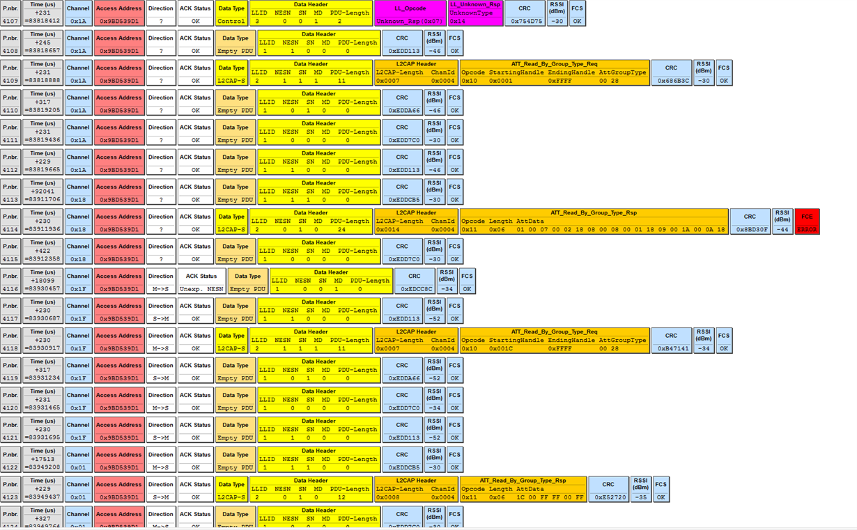
    I finally got a sniffer and here is the log.If you want some more detailed, I also uploaded a psd file.

     SNIFFLOG.psd

  • Hi Alex,

    I am not able to download the psd file, can you try up-loading it again?

    I don't see any unexpected behavior in the screen shots you have posted.
  • Hi Marie H

    I can download the log file from my last post, so I don't know why you can't.

    I up-loaded it again and please try once more.

    1055.SNIFFLOG.psd

  • Hi Alex,

    Thank you now I was able to download it.

    From the sniffer log, it seems like the slave device stops answering to connection events after packet 4211. The master keeps sending connection events.

    What happens on the slave side? Is it a HWI exception? (Can you try using a debug session and pausing when this happen.)
  • Hi Marie H

    There is an exception indeed and we have discussed it before, but I don't know why does this happen after I add some simple DMA code.

    I wonder if there is any difference between the app I used and yours on the interaction with slave devices, since you cannot reproduce this issue.

  • Hi Alex,

    I will try to find an android device and try to reproduce the issue. Because of Easter I probably won't be able to get back to until next week.
  • Can you tell me what smart phone model you are using?
  • Hi Marie H

    I don't understand the meaning of the smartphone model that you mentioned. Can you be more specific?

    Alex

  • Hi ALex,

    Exactly what android device are you using when you see the issue?
  • Hi Alex,

    do you release the power dependency anywhere ( PowerCC26XX_PERIPH_UDMA )
  • Hi Marie H

    As the test code I provided before, "Power_releaseDependency(PowerCC26XX_PERIPH_UDMA)" haven't been used.

    Alex

  • Hi Alex,

    Sorry for the delayed answer.

    You should always make sure to release dependencies that you set (when you are finished using this peripheral).

    Exactly what android device are you using when you see the issue?
  • Hi,

    I didn't release dependencies because I just used it to reproduce the issue, and the device will stuck upon next connection so I don't think whether release dependencies or not is the cause to this issue.

    I have tried several  android phones and with some of them can reproduce the issue while with the others I cannot connect to the device even for the first time.

    So I think you can get ble scanner from Google Play with a handy  android phone and perhaps you may reproduce the issue.

    To be clear, I tested with Meizu 15 Plus for the most times.

  • Hi Alex,

    The issue is due to you DMA implementation. DMA relies on the control table always being on the same memory address. You should use the ALLOCATE_CONTROL_TABLE_ENTRY macro found in UDMACC26XX.h.

    You can find a code snippet for how to use this in the DMA example I posted earlier.
  • Hi Marie H,

    I used the DMA driver lib and I foud functions uDMAControlBaseSet and uDMAChannelControlSet have the same effect with the ALLOCATE_CONTROL_TABLE_ENTRY macro on giving a static control table address which is the UDMACC26XX_CONFIG_BASE macro.So I don't think this is the cause of the issue.

    Alex

  • Hi Alex,

    You say your application works at one optimization but not another. Memory usage is one of the main differences between the optimizations.

    You also say you get the bug not immediately when you call the code, but after a while (when you reconnect).

    This corresponds to the issue I described above. Probably some memory which is being used when connecting/reconnecting over BLE is being overwritten by the DMA. Please go over your DMA code and make changes, either according to the driverlib documentation or use the driver.
  • Hi Marie H,

    I still have one question that if it is a memory issue like you said, it should have no difference between your simple link app on ios and my ble scanner on android.

    Alex

  • Hi Alex,

    I'm not exactly sure why it is this way. Please update your DMA code.
  • Hi Marie H,

    I referred to the attachment of this answer  https://e2e.ti.com/support/wireless-connectivity/bluetooth/f/538/p/789845/2931217#2931217 and use this code 

    uint8_t ui8DMAControlTable[1024] __attribute__ ((aligned(1024)));

    to have a special memory block for DMA control table, and it works for my application.

    But I still cannot figure out the ios question I posted.

    I think you guys may perfect the comment of the driverlib code, because there is no much information about this memory block and I was totally misled and would be impossible to solve this without your reminding.

    Anyway, I am very thankful to have this problem solved and also feel sorry for bothering you so much time with my poor English.

    Alex