


Other Parts Discussed in Thread: INA188, BT-POWER-CALC
Hello,
I simply wanted to provide some additional measurements of current draw related to the standard operation of the CC2640r2 as part of the SaBLE-x-R2 module. I hope that these measurements provide insight to others trying to understand battery life and current consumption. In my application the SaBLE-x-R2 does not drive any external peripherals - no LEDs, motors, nothing. I'm running a modified version of SimplePeripheral. The following measurements were taken using a Tektronix MDO3014 connected to the output of a TI INA188. The input of the INA188 is measuring across a 1 ohm shunt resistor with the return side of the SaBLE-x-R2 connected to one side of the shunt and the other side connected to the return side (GND in this case - common is tied to earth GND) of the HP triple output power supply. The gain on the amplifier is 107. I could have used a potentiometer to bring the gain to exactly 100, but I chose to use an adjustment factor on the scope while changing the probe setting to display current rather than voltage. In this configuration, 1mV on the input is 107mV on the output, but since we're "measuring" current across the shunt, 1mA on the input is 107mA on the output as seen on the scope. The 3dB roll-off for this configuration for the amplifier is 20KHz.
This is the current draw for a single pulse shortly after applying power to the module. These pulses are spaced approximately 500mS apart
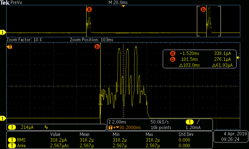
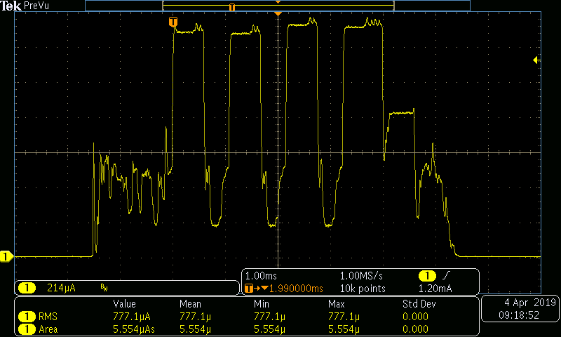
Here advertising has been turned on. Advertising pulses are separated by approximately 100mS. This varies slightly due channel hoping during advertising.

In the connected state, the pulses are repeatably 120mS apart.

Finally, after the module enters deep sleep, the only power draw is from the recharge of the capacitors (this is described in the TI literature). The timing of these pulses vary slightly, but they are generally around 500mS.
With the area data, I was able to determine the draw for each condition of the radio. Using this data, I wrote a simple C++ program to calculate the battery life based on user inputs - battery capacity and time in each radio state. As an example, I estimated the battery life of a CR2032 (I estimated the capacity to be 250mAh as found in the literature) assuming that the battery was turned on and connected within five seconds for four hours per day and was in deep sleep otherwise.
Patrick


