This thread has been locked.

If you have a related question, please click the "Ask a related question" button in the top right corner. The newly created question will be automatically linked to this question.

RTOS/CC2640: Uart is Hanging or Uart TX is not properly coming Up

Expert 1760 points
Part Number: CC2640


Tool/software: TI-RTOS

Hi guys,

Please find the scenario I'm facing in the Uart Line. Tx line is not High or Low. Even after booting or when I switch from Sleep mode ( Mode in which the Uart communication is not there and No connectable advertisements) to WakeUp mode( or Normal mode where Uart and BLE communication is fully operational) this issue is occuring.

Our product is not a standalone one. It will be powered ON by a Master with communication via UART.

In the screenshot of CRO : Yellow -> HardReset, Blue -> WakeUp pin (ext interrupt), Green -> Uart TX, Purple -> Uart RX

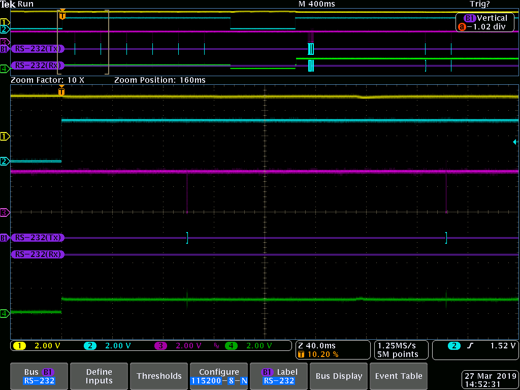
Please let me what can lead to this issue.

  • Is there any new information here compared to what is covered in e2e.ti.com/.../787924 ?
  • Not much. But need to inform my device (say Y) is not standalone , it will be inserted to another product (say X). And X and Y communicate each other through UART.
    What I observed is If I disconnect the X->Uart TX <==> Y->Uart RX, only first time when I switch from Sleep to Wakeup the TX line is not going to indefinite state. And in the next Wakeup Uart TX state is going to HIGH state. So the issue is most probably with the X where I wait for the WakUp pin interrupt and based on that I Open the Uart.
  • The pins on the chip are high-z at start-up until defined as anything else. Have you considered this in the use case?
  • Yes. We considered that. So initially in application we forcefully change some pins to Pull down. The initial pin configuration as per our use case is below:
    PIN_Config BoardGpioInitTable[] = {

    Board_UART_RX | PIN_INPUT_EN | PIN_PULLDOWN,
    Board_UART_TX | PIN_INPUT_EN | PIN_PULLDOWN,
    Board_EXTINT | PIN_INPUT_EN | PIN_PULLDOWN,
    }
  • Ok, so it looks like the UART_TX pin is low until you get the external start-up signal ( Blue -> WakeUp pin (ext interrupt))

    Could you outline what happens when the wakeup pin goes high?
  • As per our use case "When the Wakeup pin goes high, the Uart is opened (TX line will go high) and communication through UART is enabled". 

    Flow is like as follows:

    ExtInt Pin -> WakeUp pin HIGH -> Start Clock which will check for the change in state ( only if state difference is there [WakeUp Low to High]) -> Based on the state (if it is WakeUp HIGH) it will Post an event to Open Uart.

    But as of now Sometimes when the WakeUp pin goes High the UART TX pin is not going exactly high (TX pin is in-between LOW and HIGH state as per the screenshot above).

    Please let me know if you need more clarifications on this topic

    Thanks.

  • I assume that you have debugged the code and have confirmed that UART open has been run also in the cases where the TX line is in between?

    Does this happen also if you have not connected the TxD pin to something?
  • Yes. Uart is opening properly in the cases where TX line is in between.
    I couldn't remove the TxD pin connection as my module's(say X) Tx is internally connected to another device's (say Y) RX. But we made the PULLUP to NO PULL in device Y->RX, and observed that when the WakeUp pin is High then the Uart TX pin is LOW (previously in-between state).
  • "But as of now Sometimes when the WakeUp pin goes High the UART TX pin is not going exactly high (TX pin is in-between LOW and HIGH state as per the screenshot above).": If I understand you correctly from this, sometimes you get the correct level on the line. Is that correct? If so, have you been able to identify what the difference is?

    If you have a fex boards, is it possible to cut the UART line?
  • Yes. correct, most of the times I'm getting correct level (i.e, When WakeUp pin is HIGH , TX also will be High) . The inbetween state is coming in 2 places:
    1) everytime when the First Wake Up after device startup
    2) Sometimes during WakeUp (for eg: 2 times in 10 Wakeup transitions)
    In both the above cases a Re-Wakeup solves the issue (means when I observe the Tx in between state, again if I do a WakeUp Low to High results in the correct level of TX)

    Unfortunately not able to cut the Uart line as the module board(X) sits in another device board(Y).

  • What is done differently between case 1) and 2) ?

    It could look like something is not set/ run correctly the first time you do a wakeup but that is set in a later wakeup. You have to go through your code base and check what is done/ set differently.
  • case 1 and case2 are different positions of the same code. The issue is persisting not only during the first time wakeup but also later stages (case2) eventhough not much frequently.
    But my doubt is how a rewakeup (or making Wakeup low and then making Wakeup High) solves the issue if there is some problem with Wakeup handling in code?
  • Have you at any point checked what the IO registers are set to in the different cases?
  • Not checked the IO registers.

    Can you please elaborate your question what exactly you mean to check and how?

  • IO registers status:
    The Input Enable register (IE) of the IOCFG is 1(while UART close) and 0 (Uart Open) for TX , but in RX line IE will always be 1.
    When UART is Open PULL_CTL reg = 0x03 (means NO PULL) and when UART is Closed PULL_CTL reg = 0x01 (PULL_DOWN) .

    One more scenario I observed is Uart_Close is called 2 times continuously (or simultaneously) without Opening the Uart after a Uart_Close. Will this have any effect on my issue?.
    Thanks.
  • For the register values: Not clear from the above if you see a difference when the the UART lines are at the expected level vs not.

    "One more scenario I observed is Uart_Close is called 2 times continuously (or simultaneously) without Opening the Uart after a Uart_Close. "
    - Why do you call UART_close more than once?

    Not sure what happens if you try to close the driver more than once, you have to look at the driver code. Not sure if the handle will be valid the second time and what this could lead to.
  • I'll make it clear => I don't mean that in code I'm calling the UART_close more than once, but when I debugged I observed that control is coming to UART_close more than once. Does it make clear now?

    Second time the handle is not valid and a false condition (just a debugging point) is executed.

    One more doubt I have is "Is it a normal case --> the Uart TX line is getting Reconfigured as Input and Output every time when UART_open and UART_close ?"

  • "but when I debugged I observed that control is coming to UART_close more than once. Does it make clear now?": Not really. Why is the UART_close done more than once?

    Have you looked into the UART driver and seen what is done by the driver when you run open/ close?
  • I don't mean that I'm forcefully making the Uart_Close more than once. Im just posting an Uart_Event when my device is going to Sleep mode (low power mode).
    And it won't call Uart_Close (driver function) because once I close the Uart, it won't again close the same Uart again until a Uart_Open is called (checking for the condition whether Uart is Open or not).
  • If that is the case, how is what you wrote here: "One more scenario I observed is Uart_Close is called 2 times continuously (or simultaneously) without Opening the Uart after a Uart_Close." true?
  • It is a mistake in how I narrated the issue. If that misleaded you im sorry.
    One more scenario I observed is Uart_Close is called (instead please make it Uart Event is posted) 2 times continuously (or simultaneously) without Opening the Uart after a Uart_Close."
  • Based on what you write it sounds like you have an issue with the execution flow in your code that could easily cause a strange state. Without the code it's not possible for us to pinpoint what is going on.