This thread has been locked.

If you have a related question, please click the "Ask a related question" button in the top right corner. The newly created question will be automatically linked to this question.

RTOS/CC2640R2F: Unable to use TDI and TDO as gpio pins in CC2460R2F chip set

Part Number: CC2640R2F

Tool/software: TI-RTOS

Hi 

Issue : Unable to use TDI and TDO as gpio pins .

Form the document I came to know   that TDI and TDO can be used as GPIOs, and  TCK and TMS are JTAG only.

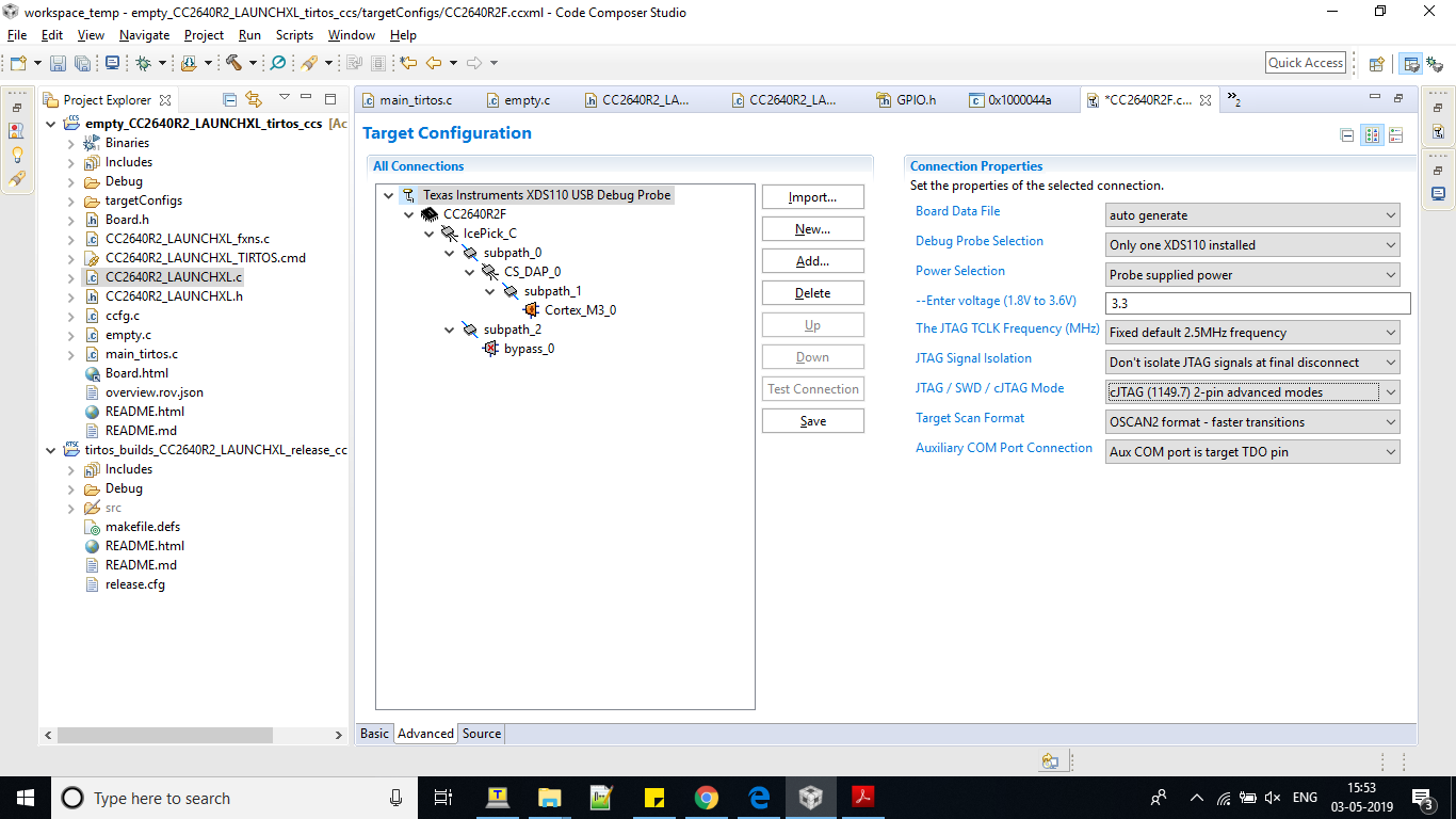
In CC2640R2F.ccxml file configures the cjag as 2-pins, find the image below 


Software Changes : 

In CC2640R2_LAUNCHXL.c added the below lines 

GPIO_PinConfig gpioPinConfigs[] = {

--

/* Output pins */
GPIOCC26XX_DIO_17 | GPIO_DO_NOT_CONFIG, /* TDI LED     Array Index 11 */
GPIOCC26XX_DIO_16 | GPIO_DO_NOT_CONFIG, /* TDO LED   Array Index 12 */

}

void *mainThread(void *arg0)
{
/* 1 second delay */
uint32_t time = 1;

/* Call driver init functions */
GPIO_init();

/* Configure the LED pin */
GPIO_setConfig(12, GPIO_CFG_OUT_STD | GPIO_CFG_OUT_LOW);

/* Turn on user LED */
GPIO_write(12, Board_GPIO_LED_ON);

while (1) {
sleep(time);
GPIO_toggle(12);
}
}

Please clarify I am missing any thing .

  • I assume that your code didn't toggle the LED since you posted this question.

    Does your code work for the DIO pins except for DIO 16 and 17?

    Also see e2e.ti.com/.../711372 on how to add a new DIO.
  • Hi ,

    My Code works for DIO pins other than DIO 16 an 17 .
    I am able to toggle DIO 6 and DIO 7 . Except DIO 16 and 17 which are jtags TD0 and TDI .

    Here are the software changes .

    In the CC2640R2_LAUNCHXL.c file for the following table, the changes done are

    const PIN_Config BoardGpioInitTable[] = {
    CC2640R2_LAUNCHXL_PIN_RLED | PIN_GPIO_OUTPUT_EN | PIN_GPIO_LOW | PIN_PUSHPULL | PIN_DRVSTR_MAX, /* LED initially off */
    CC2640R2_LAUNCHXL_PIN_GLED | PIN_GPIO_OUTPUT_EN | PIN_GPIO_LOW | PIN_PUSHPULL | PIN_DRVSTR_MAX, /* LED initially off */
    CC2640R2_LAUNCHXL_PIN_BTN1 | PIN_INPUT_EN | PIN_PULLUP | PIN_IRQ_BOTHEDGES | PIN_HYSTERESIS, /* Button is active low */
    CC2640R2_LAUNCHXL_PIN_BTN2 | PIN_INPUT_EN | PIN_PULLUP | PIN_IRQ_BOTHEDGES | PIN_HYSTERESIS, /* Button is active low */
    CC2640R2_LAUNCHXL_SPI_FLASH_CS | PIN_GPIO_OUTPUT_EN | PIN_GPIO_HIGH | PIN_PUSHPULL | PIN_DRVSTR_MIN, /* External flash chip select */
    CC2640R2_LAUNCHXL_UART_RX | PIN_INPUT_EN | PIN_PULLDOWN, /* UART RX via debugger back channel */
    CC2640R2_LAUNCHXL_UART_TX | PIN_GPIO_OUTPUT_EN | PIN_GPIO_HIGH | PIN_PUSHPULL, /* UART TX via debugger back channel */
    CC2640R2_LAUNCHXL_SPI0_MOSI | PIN_INPUT_EN | PIN_PULLDOWN, /* SPI master out - slave in */
    CC2640R2_LAUNCHXL_SPI0_MISO | PIN_INPUT_EN | PIN_PULLDOWN, /* SPI master in - slave out */
    CC2640R2_LAUNCHXL_SPI0_CLK | PIN_INPUT_EN | PIN_PULLDOWN, /* SPI clock */
    CC2640R2_LAUNCHXL_DIO16_TDO | PIN_GPIO_OUTPUT_EN | PIN_GPIO_LOW | PIN_PUSHPULL | PIN_DRVSTR_MAX,
    CC2640R2_LAUNCHXL_DIO17_TDI | PIN_GPIO_OUTPUT_EN | PIN_GPIO_LOW | PIN_PUSHPULL | PIN_DRVSTR_MAX,
    PIN_TERMINATE
    };


    GPIO_PinConfig gpioPinConfigs[] = {
    /* Input pins */
    GPIOCC26XX_DIO_13 | GPIO_DO_NOT_CONFIG, /* Button 0 */
    GPIOCC26XX_DIO_14 | GPIO_DO_NOT_CONFIG, /* Button 1 */

    GPIOCC26XX_DIO_15 | GPIO_DO_NOT_CONFIG, /* CC2640R2_LAUNCHXL_SPI_MASTER_READY */
    GPIOCC26XX_DIO_21 | GPIO_DO_NOT_CONFIG, /* CC2640R2_LAUNCHXL_SPI_SLAVE_READY */

    /* Output pins */
    GPIOCC26XX_DIO_07 | GPIO_DO_NOT_CONFIG, /* Green LED */
    GPIOCC26XX_DIO_06 | GPIO_DO_NOT_CONFIG, /* Red LED */

    /* SPI Flash CSN */
    GPIOCC26XX_DIO_20 | GPIO_DO_NOT_CONFIG,

    /* SD CS */
    GPIOCC26XX_DIO_21 | GPIO_DO_NOT_CONFIG,

    /* Sharp Display - GPIO configurations will be done in the Display files */
    GPIOCC26XX_DIO_24 | GPIO_DO_NOT_CONFIG, /* SPI chip select */
    GPIOCC26XX_DIO_22 | GPIO_DO_NOT_CONFIG, /* LCD power control */
    GPIOCC26XX_DIO_23 | GPIO_DO_NOT_CONFIG, /*LCD enable */

    GPIOCC26XX_DIO_16 | GPIO_DO_NOT_CONFIG,
    GPIOCC26XX_DIO_17 | GPIO_DO_NOT_CONFIG,


    };

    In CC2640R2_LAUNCHXL.h file the changes done are
    typedef enum CC2640R2_LAUNCHXL_GPIOName {
    CC2640R2_LAUNCHXL_GPIO_S1 = 0,
    CC2640R2_LAUNCHXL_GPIO_S2,
    CC2640R2_LAUNCHXL_SPI_MASTER_READY,
    CC2640R2_LAUNCHXL_SPI_SLAVE_READY,
    CC2640R2_LAUNCHXL_GPIO_LED_GREEN,
    CC2640R2_LAUNCHXL_GPIO_LED_RED,
    CC2640R2_LAUNCHXL_GPIO_SPI_FLASH_CS,
    CC2640R2_LAUNCHXL_SDSPI_CS,
    CC2640R2_LAUNCHXL_GPIO_LCD_CS,
    CC2640R2_LAUNCHXL_GPIO_LCD_POWER,
    CC2640R2_LAUNCHXL_GPIO_LCD_ENABLE,
    CC2640R2_LAUNCHXL_GPIO_16_TDO,
    CC2640R2_LAUNCHXL_GPIO_17_TDI,
    CC2640R2_LAUNCHXL_GPIOCOUNT
    } CC2640R2_LAUNCHXL_GPIOName;


    In Board.h file the changes added the below llines .
    #define Board_GPIO_TDO CC2640R2_LAUNCHXL_GPIO_16_TDO
    #define Board_GPIO_TDI CC2640R2_LAUNCHXL_GPIO_17_TD1

    In CC2640R2_LAUNCHXL.h already we have the definition below .
    #define CC2640R2_LAUNCHXL_DIO16_TDO IOID_16
    #define CC2640R2_LAUNCHXL_DIO17_TDI IOID_17


    void *mainThread(void *arg0)
    {
    /* 1 second delay */
    uint32_t time = 1;

    /* Call driver init functions */
    GPIO_init();

    /* Configure the LED pin */
    GPIO_setConfig(Board_GPIO_LED0, GPIO_CFG_OUT_STD | GPIO_CFG_OUT_LOW);
    GPIO_setConfig(Board_GPIO_LED1, GPIO_CFG_OUT_STD | GPIO_CFG_OUT_LOW);
    GPIO_setConfig(Board_GPIO_TDO, GPIO_CFG_OUT_STD | GPIO_CFG_OUT_LOW);
    GPIO_setConfig( Board_GPIO_TDI , GPIO_CFG_OUT_STD | GPIO_CFG_OUT_LOW);

    /* Turn on user LED */
    GPIO_write(Board_GPIO_LED0, Board_GPIO_LED_ON);
    GPIO_write(Board_GPIO_LED1, Board_GPIO_LED_ON);
    GPIO_write(Board_GPIO_TDO, Board_GPIO_LED_ON);
    GPIO_write( Board_GPIO_TDI , Board_GPIO_LED_ON);

    while (1) {
    sleep(time);
    GPIO_toggle(Board_GPIO_LED0);
    GPIO_toggle(Board_GPIO_LED1);
    GPIO_toggle(Board_GPIO_TDO);
    GPIO_toggle( Board_GPIO_TDI );
    }
    }

    I think I am following the wright procedure . Kindly guide me .
  • How do you measure? Note that DIO16 and DIO17 are not connected by default to the pin row on the side on the LP, you have to use a 0 ohm resistor to do this.

    I got this to work adding the following changes to the empty project:

    typedef enum CC2640R2_LAUNCHXL_GPIOName {
        CC2640R2_LAUNCHXL_GPIO_S1 = 0,
        CC2640R2_LAUNCHXL_GPIO_S2,
        CC2640R2_LAUNCHXL_SPI_MASTER_READY,
        CC2640R2_LAUNCHXL_SPI_SLAVE_READY,
        CC2640R2_LAUNCHXL_GPIO_LED_GREEN,
        CC2640R2_LAUNCHXL_GPIO_LED_RED,
        CC2640R2_LAUNCHXL_GPIO_TMP116_EN,
        CC2640R2_LAUNCHXL_GPIO_SPI_FLASH_CS,
        CC2640R2_LAUNCHXL_SDSPI_CS,
        CC2640R2_LAUNCHXL_GPIO_LCD_CS,
        CC2640R2_LAUNCHXL_GPIO_LCD_POWER,
        CC2640R2_LAUNCHXL_GPIO_LCD_ENABLE,
        CC2640R2_LAUNCHXL_GPIO_TDO,
        CC2640R2_LAUNCHXL_GPIO_TDI,
        CC2640R2_LAUNCHXL_GPIOCOUNT
    } CC2640R2_LAUNCHXL_GPIOName;

    GPIO_PinConfig gpioPinConfigs[] = {
        /* Input pins */
        GPIOCC26XX_DIO_13 | GPIO_DO_NOT_CONFIG,  /* Button 0 */
        GPIOCC26XX_DIO_14 | GPIO_DO_NOT_CONFIG,  /* Button 1 */
    
        GPIOCC26XX_DIO_15 | GPIO_DO_NOT_CONFIG,  /* CC2640R2_LAUNCHXL_SPI_MASTER_READY */
        GPIOCC26XX_DIO_21 | GPIO_DO_NOT_CONFIG,  /* CC2640R2_LAUNCHXL_SPI_SLAVE_READY */
    
        /* Output pins */
        GPIOCC26XX_DIO_07 | GPIO_DO_NOT_CONFIG,  /* Green LED */
        GPIOCC26XX_DIO_06 | GPIO_DO_NOT_CONFIG,  /* Red LED */
        GPIOCC26XX_DIO_30 | GPIO_DO_NOT_CONFIG,  /* TMP116_EN */
    
        /* SPI Flash CSN */
        GPIOCC26XX_DIO_20 | GPIO_DO_NOT_CONFIG,
    
        /* SD CS */
        GPIOCC26XX_DIO_21 | GPIO_DO_NOT_CONFIG,
    
        /* Sharp Display - GPIO configurations will be done in the Display files */
        GPIOCC26XX_DIO_24 | GPIO_DO_NOT_CONFIG, /* SPI chip select */
        GPIOCC26XX_DIO_22 | GPIO_DO_NOT_CONFIG, /* LCD power control */
        GPIOCC26XX_DIO_23 | GPIO_DO_NOT_CONFIG, /*LCD enable */
        GPIOCC26XX_DIO_16 | GPIO_DO_NOT_CONFIG, /*TDO enable */
        GPIOCC26XX_DIO_17 | GPIO_DO_NOT_CONFIG, /*TDI enable */
    };

        while (1) {
            sleep(time);
            GPIO_toggle(Board_GPIO_LED0);
            GPIO_toggle(CC2640R2_LAUNCHXL_GPIO_TDO);
            GPIO_toggle(CC2640R2_LAUNCHXL_GPIO_TDI);
        }