Tool/software: TI-RTOS
Hello,
SDK : 2.4
I'm having a hard time making the ADCSingleChannel example work with a 5X5 chip.
First, i made it work with a 7X7 with the launchPad without any problems.
To make it work with a 5X5, i have commented the pin table to make sur no pin above IOID_14 get used
const PIN_Config BoardGpioInitTable[] = {

//    CC2640R2_LAUNCHXL_PIN_RLED | PIN_GPIO_OUTPUT_EN | PIN_GPIO_LOW | PIN_PUSHPULL | PIN_DRVSTR_MAX,       /* LED initially off */
//    CC2640R2_LAUNCHXL_PIN_GLED | PIN_GPIO_OUTPUT_EN | PIN_GPIO_LOW | PIN_PUSHPULL | PIN_DRVSTR_MAX,       /* LED initially off */
//    CC2640R2_LAUNCHXL_PIN_BTN1 | PIN_INPUT_EN | PIN_PULLUP | PIN_IRQ_BOTHEDGES | PIN_HYSTERESIS,          /* Button is active low */
//    CC2640R2_LAUNCHXL_PIN_BTN2 | PIN_INPUT_EN | PIN_PULLUP | PIN_IRQ_BOTHEDGES | PIN_HYSTERESIS,          /* Button is active low */
//    CC2640R2_LAUNCHXL_SPI_FLASH_CS | PIN_GPIO_OUTPUT_EN | PIN_GPIO_HIGH | PIN_PUSHPULL | PIN_DRVSTR_MIN,  /* External flash chip select */
//    CC2640R2_LAUNCHXL_UART_RX | PIN_INPUT_EN | PIN_PULLDOWN,                                              /* UART RX via debugger back channel */
//    CC2640R2_LAUNCHXL_UART_TX | PIN_GPIO_OUTPUT_EN | PIN_GPIO_HIGH | PIN_PUSHPULL,                        /* UART TX via debugger back channel */
//    CC2640R2_LAUNCHXL_SPI0_MOSI | PIN_INPUT_EN | PIN_PULLDOWN,                                            /* SPI master out - slave in */
//    CC2640R2_LAUNCHXL_SPI0_MISO | PIN_INPUT_EN | PIN_PULLDOWN,                                            /* SPI master in - slave out */
//    CC2640R2_LAUNCHXL_SPI0_CLK | PIN_INPUT_EN | PIN_PULLDOWN,                                             /* SPI clock */

    PIN_TERMINATE
};
Then, i have updated the ADC Configuration as followed :
#include <ti/drivers/ADC.h>
#include <ti/drivers/adc/ADCCC26XX.h>
ADCCC26XX_Object adcCC26xxObjects[CC2640R2_LAUNCHXL_ADCCOUNT];
const ADCCC26XX_HWAttrs adcCC26xxHWAttrs[CC2640R2_LAUNCHXL_ADCCOUNT] = {
{
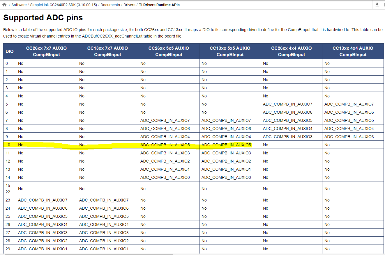
.adcDIO = IOID_10,
.adcCompBInput = ADC_COMPB_IN_AUXIO4,
.refSource = ADCCC26XX_FIXED_REFERENCE,
.samplingDuration = ADCCC26XX_SAMPLING_DURATION_2P7_US,
.inputScalingEnabled = true,
.triggerSource = ADCCC26XX_TRIGGER_MANUAL,
.returnAdjustedVal = false
}
};
const ADC_Config ADC_config[CC2640R2_LAUNCHXL_ADCCOUNT] = {
{&ADCCC26XX_fxnTable, &adcCC26xxObjects[CC2640R2_LAUNCHXL_ADC0], &adcCC26xxHWAttrs[CC2640R2_LAUNCHXL_ADC0]},
};
const uint_least8_t ADC_count = CC2640R2_LAUNCHXL_ADCCOUNT;
typedef enum CC2640R2_LAUNCHXL_ADCName {
    CC2640R2_LAUNCHXL_ADC0 = 0,
    CC2640R2_LAUNCHXL_ADCCOUNT
} CC2640R2_LAUNCHXL_ADCName;
When i run the code with this config, i don't have any crash, but all the values i read are 3.3V event though my IOID_10 pin is tied to ground ( or to any other values ).
I'm doing something wrong in my configuration for the 5X5 chip, but i have no idea what.
Any clue or help is greatly appreciated.