This thread has been locked.

If you have a related question, please click the "Ask a related question" button in the top right corner. The newly created question will be automatically linked to this question.

CC2640R2F: Inductor Orientation at Single Ended RF External Bias?

Part Number: CC2640R2F

Hi,

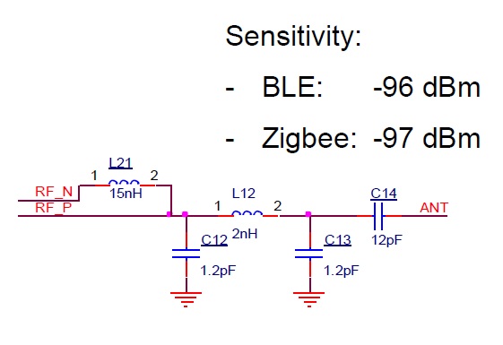
   Would there be any bad effects in RF if for example the inductors have been placed by PCB manufacturer with wrong orientation maybe reversed? I read the Murata post below and different inductor orientations outputs different inductance value.

https://www.murata.com/en-sg/products/emiconfun/inductor/2012/05/14/en-20120514-p1

-kel

  • I assume that you mean position 2 instead of position 1 with reference to the article? If that is the case I would assume that the impact of the wrong orientation is less than the component tolerance and hence you should not be able to see any impact.

    If they have just mounted one the wrong way and this is in the balun, the balun could be slightly more not balanced since RF_P will see a slightly different value than RF_N.

    We have not tested with both orientations.
  • Hi TER,

    This is the Single Ended RF External Bias Configuration. As you can see 2 inductors indicates Pin 1 and Pin 2. What If the PCB Manufacturer mounted the inductors reversed, what is the impact in RF?

    -kel

  • As said I would assume that the impact is minimal but since we haven't measured this we can't know for sure.

    Have you done any measurements on this?
  • No, we just finished PCB design and we just worried if that might happen during PCB Manufacturing. Anyway, thanks I will mark this post as "Answered".

    -kel