This thread has been locked.

If you have a related question, please click the "Ask a related question" button in the top right corner. The newly created question will be automatically linked to this question.

CC2640R2F: IQ Amplitude Variation and inconsistency between Antennas

Part Number: CC2640R2F

Hi,

We're analyzing IQ data from three antennas ( BOOSTXL-AoA) respectively

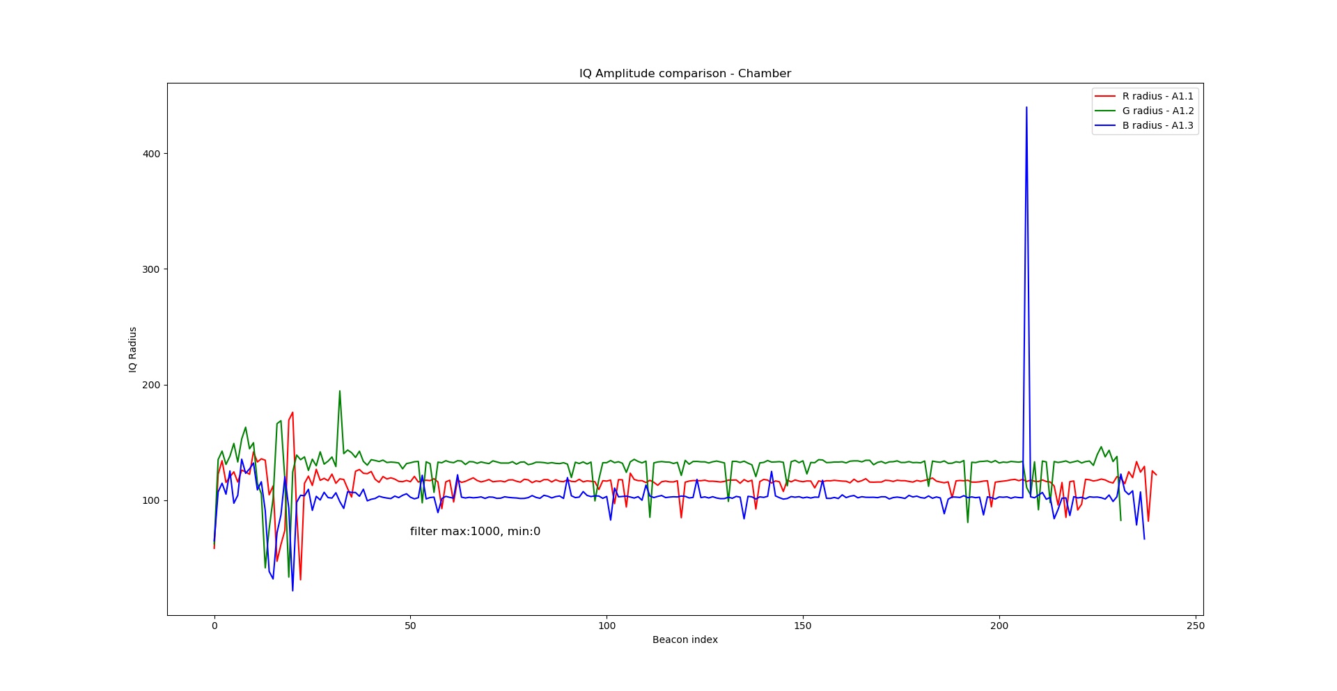
Collected chamber data shows that there's Amplitude difference between these antennas (refer to fig. below)

What might be the causes of such Amplitude Variation and inconsistency between antennas?  ( Antenna gain, switch timing, AGC bandwidth?)

We wanna deep dive on this for better AoA calculation

Thanks

Aaron

  • Hi Aaron,

    Since the BOOSTXL-AoA board have three different antennas it's not unexpected that you will see variation in the amplitude from the different antennas. Even though the three antennas are equal the environment around them is not 100% equal. A1.1 have A1.2 on one side and air on the other side while A1.2 have an antenna on both sides. A1.3 is more similar as A1.1 but not 100%. This will lead to small variation in the efficiency of the antenna which again will affect the amplitude. The loss from the three antenna through the balun, pcb traces and RF switches is also not 100% equal and this will lead to amplitude variations.
    If you need the amplitude to be 100% equal between the antennas I think you need to do some calibration of the HW.

    One question, is your transmitter exactly 0 degrees on your receiver? If not, that will also give amplitude variations between the antennas.


    Best Regards,
    R.M
  • R.M said:
    A1.1 have A1.2 on one side and air on the other side while A1.2 have an antenna on both sides. A1.3 is more similar as A1.1 but not 100%.

    Hi R.M,

    Thanks for your explanation.

    Not sure whether my understanding is correct, do you mean on BOOSTXL-AoA (HW Rev.A) ONLY A1.2 have antenna on both sides while A1.1&A1.3 only have one side?

    And yes, the transmitter is 0 degree on Antenna A1 (not the whole device including A1, A2)

    One more question, do you think that this IQ Amplitude Variation and inconsistency will affect the phase difference between Antennas and lead to miscalculated AoA ultimately? 

    If so, how can we proceed this calibration of the HW and does TI have standard procedure for this like angle compensation?

    Thanks~ :)

  • Hi Aaron,

    If you look at the BOOSTXL-AoA board you see that antenna A1.2 is in the middle of the antenna array and have antenna A1.1 on one side and antenna A1.3 on the other side. A1.1 have only A1.2 on one side and nothing on the other side and the same goes for A1.3.

    Since we only care about the phase of the signal for AoA and not the magnitude this amplitude variation should not affect your AoA results.

    Best Regards,
    R.M