This thread has been locked.

If you have a related question, please click the "Ask a related question" button in the top right corner. The newly created question will be automatically linked to this question.

CCS/CC2650: CCS/CC2650

Part Number: CC2650

Tool/software: Code Composer Studio

Hello,

I've been trying to upload code to a custom board I've built using the CC2650 (32 pin, model RHBT) - the schematic is based off of TI's sensor tag schematic. I've managed to upload example code (PWM example from the TI-RTOS examples) successfully to the 2650 SensorTag kit and the 2650 LaunchPad using CCS, but when I try and upload it to my board using the the JTAG port from the Debugger DevPack, I'm getting this issue 

Error connecting to the target:

(Error -242 @ 0x0)

A router subpath could not be accessed.

The board configuration file is probably incorrect.

(Emulation package 8.1.0.00005)

Image.tiff

Which worries me, because I get the same error when the debugger is not plugged into anything at all. I've triple checked my JTAG connections and the power supply traces to the 2650, which all appear to be working fine. I've tried uploading example code from the CC2650_5XD example set since the 2650 model on the 5xd kit is also 32 pin, so I figured the pin mapping would be the same - perhaps this wasn't the best idea.

Am I missing something obvious? Should I not be using the DevPack for this? Or does anyone have any suggestions on how to get past this? Any ideas are appreciated.

Thanks!

  • Also, apologies if this is the second time you're seeing this post. I posted this before but wasn't able to respond for a few days so it became locked.
  • Yes, it’s no problem to use CC-DEVPACK-DEBUGGER. Make sure your JTAG connection is correct and good, and your CC2650 is well powered.
  • Hi Connor,

    Can you share your schematic, layout and a photo of how your board is connected to the debugger?

    Regards,
    Fredrik
  • I am closing this thread due to inactivity.
  • Hi Connor,

    I see you rejected the last reply. If you need more help on this, you need to provide more details on your setup.

    Regards,
    Fredrik
  • Hi Fredrik,

    My apologies for the late reply - I haven't had a chance to check for a response for the past few days. Thanks for getting back to me, though.

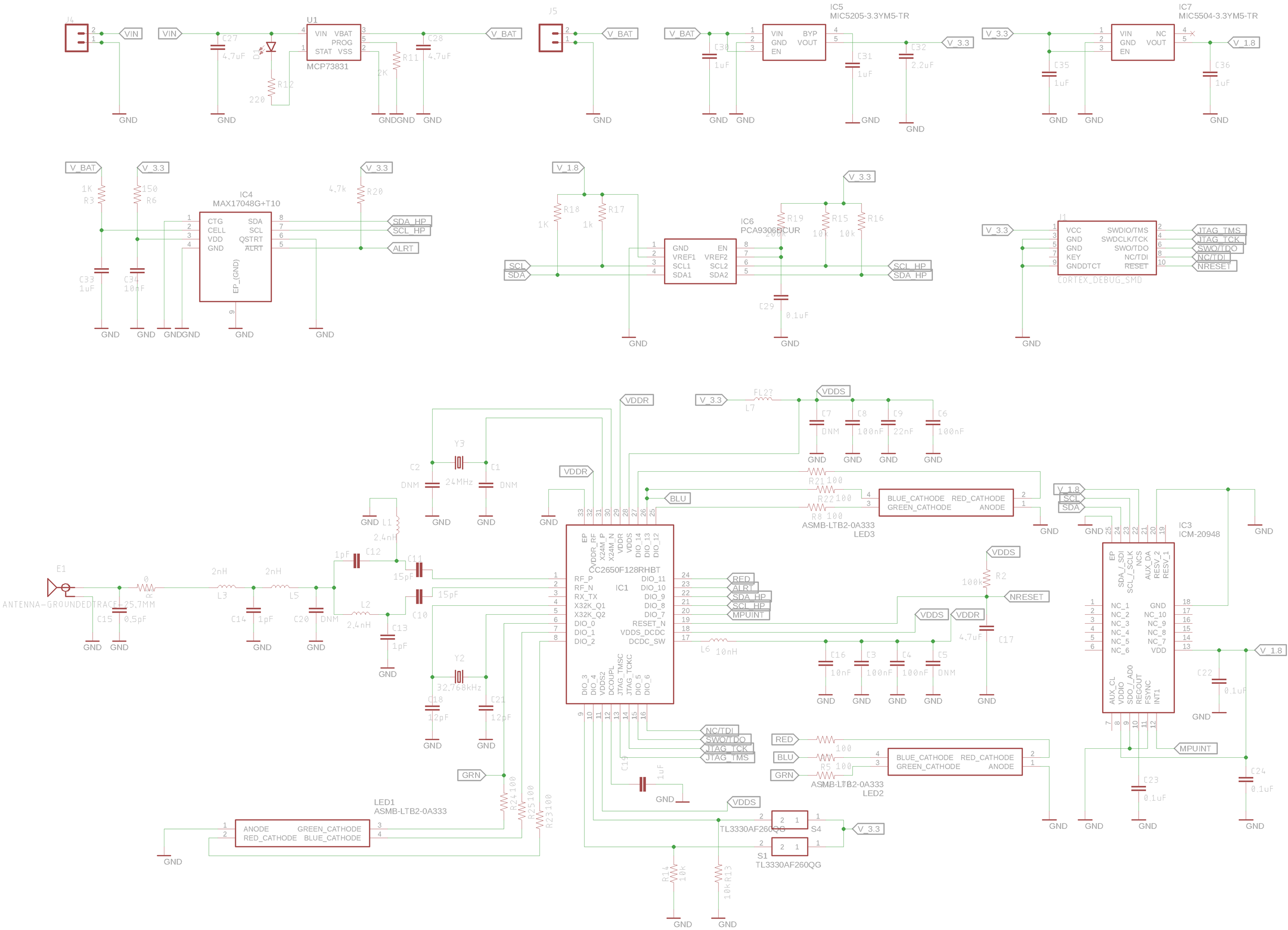
    The schematic used is based off of the SensorTag - I've included it below.

    Since I posted this, I've had more time to try and debug the system. As suggested, I moved away from the SensorTag DevPack debugger to the XDS110 on TI's CC2650 LaunchPad. It's a direct JTAG connection from the launch pad to our board, and the pin connections are shown in the schematic below.

    I read that the 1uF decoupling cap off of pin 12 is supposed to be reading 1.27V - when I take a new board and measure the voltage across the cap (before ever attempting to debug/program it), it comes to the expected 1.2-1.3V. After connecting to the debugger over JTAG, it still reads 1.27V and I get a new error message that says it's "Unable to access DAP". After unplugging the XDS110 from my computer and plugging it back in, I measure 0V across the decoupling cap and I start getting the "Router subpath could not be accessed" error again. I'd assume that somehow unplugging the device blew the internal regulator?

    If you see anything concerning in the schematic, please let me know. I appreciate your help!

  • Hi Connor,

    The values for the DCDC decoupling and output components are incorrect. The schematic says 22 nF and 10 nH, but the values should be 22 uF and 10 uH (as in micro-).

    What voltage do you measure on VDDR on the failing boards?

    Regards,
    Fredrik
  • Hi Fredrik,

    Oh goodness, can't believe we missed that. Good catch!

    I measured VDDR at 2.2V on some boards, and 0 on others that had failed. Let me change the components to what they should be and I'll post what happens.

    Cheers,

    Connor