This thread has been locked.

If you have a related question, please click the "Ask a related question" button in the top right corner. The newly created question will be automatically linked to this question.

CC2640R2F: How to get 0dBm from LAUNCHXL-CC2640R2 with SmartRF Studio 7?

Part Number: CC2640R2F
Other Parts Discussed in Thread: LAUNCHXL-CC2640R2, , CC2650, LAUNCHXL-CC2650

Hello,

I'm working on our custom board that has CC2640R2F and this is compatible with LAUNCHXL-CC2640R2.

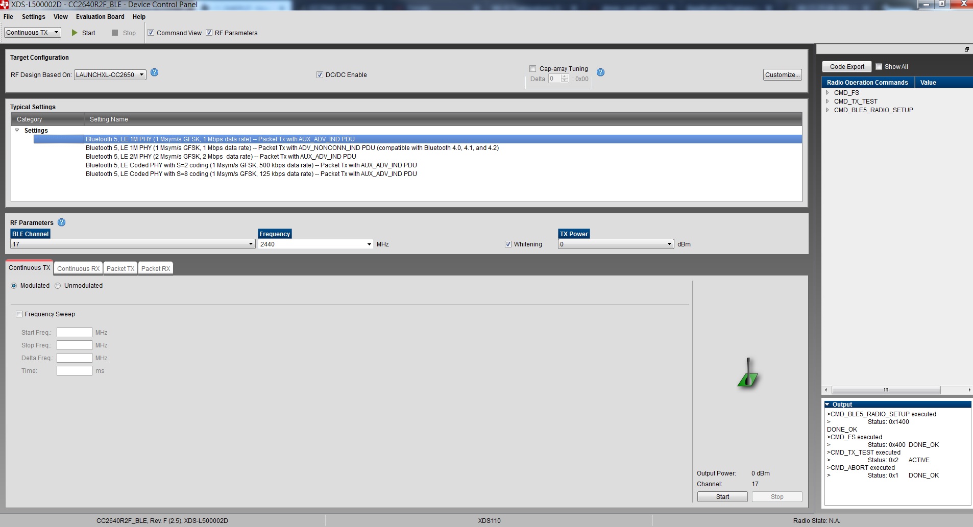
At our Radio certificates such like FCC, we have to generate specific frequency like 2440MHz, unmodurated, 0dBm continuous Tx.

I have configured SmartRF Studio 7 (Version 2.13.1) to get this RF wave but, our spectrum analyzer shows around -30dBm. I supposed it would have

cable loss between LAUNCHXL and a Spectrum Analyzer this should be around 2-3 dBm. So it shall become -3dBm if we set

0dBm on CC2640R2F. Their equipment are calibrated because we found to get correct 0dBm with SENTORTAG (CC2650 7x7) and CC2650EM-7ID config.

Can you tell me how to configure 0dBm (or 5dBm) as TxPower for CC2640R2F on SmartRF Studio? We couldn't find

"LAUNCHXL-CC2640R2" at RF design based on list. So I tried to pick CC2640EM-CXS or another on this list, copy and modified, however, never get luck.

I think we have to have correct configuration file for LAUNCHXL-CC2640R2.   Please advise.

  • Hi Tom,

    If you have configured your custom HW for differential RF with internal bias, you can either use the CC2650EM-7ID or LAUNCHXL-CC2650 target configurations.

    If you are seeing an output power of -30 dBm, something is definitely wrong in your setup. Can you share your schematic and layout? A snippet of the CC2640R2F and supporting passive components is sufficient.

    Regards,
    Fredrik
  • Hi YK,

    Thanks for your post. But this issue is not resolved.

    As I said, your configuration shows around -30dBm (0.002mW) with LAUNCHXL-CC2640R2.

    Please find below as a spectrum on them.

  • Hello Fredrik,

    Yes -  but I can show you this issue with LAUNCHXL-CC2640R2 and CC2650EM-7ID config.   You're right this is

    definitely wrong it shows -30dBm while I tried to config internal/external bias and diff/single-end RF of course.

    I supposed values of register for TxPower is wrong, which is different from CC2650.

    Please find our schematic below;

  • Hi Tom,

    The TxPower values are the same for CC2650 and CC2640R2F. Your HW is configured for differential RF with internal bias, there is no point in testing other SW configurations.

    Are you sure your RF connector is mounted the correct way? If it is rotated 180 degrees you would probably see a power loss around 30 dB.

    Can you also share your layout, and perhaps a photo of your actual board?

    Regards,
    Fredrik
  • Hello Fredrik,

    Thank you so much for your supporting us!

    Do you mean the RF connector has direction or polarity to mount on PCB? That RF connector on a LAUNCHXL-CC2640R2 doesn't have switch between IC and ANT so,

    I don't think it has. Please find attached two pics; one is SMA adapter on LAUNCHXL-CC2640R2 and other is our board.

    Regards,

    Tom

  • Hi Tom,

    The JSC RF connector used on the LaunchPad does not have polarity. To use it, you must however change the orientation of the DC blocking capacitor as this is also used to select either the PCB antenna or the connector. In the photo you have attached, the capacitor is oriented towards the PCB antenna, and this will give approximately 30 dB attenuation on the RF connector.

    The RF connector used on your board definitely has polarity. When the RF cable is connected, one terminal will be connected to the cable and the other terminal will be disconnected. It is important the the terminal going to the cable is directed towards the RF output of the IC. If you have mounted the connector the wrong way, the cable will be connected to the antenna and not the RF output. Page 4 in the datasheet will explain this in more detail: no.mouser.com/.../MS-156HF_catalog-939544.pdf

    If you provide a picture of your board without the SMA adapter, I can tell you whether the connector is mounted correctly or not.

    Regards,
    Fredrik

  • One more thing, I cannot see C32 and C33 on your PCB. Is the schematic you posted representative for the actual design?
  • Hello Fredrik,

    Thank you so much for your advise.

    >> The RF connector used on your board definitely has polarity. 

    Now I understand this. Thanks again for your help. You are correct, we have mounted RF connector which was wrong way. Also LaunchPad was not modified for it.

    >> One more thing, I cannot see C32 and C33 on your PCB. Is the schematic you posted representative for the actual design?

    Yes, but C32 and C33 can hardly see so these are so small for me in these days ^^);