This thread has been locked.

If you have a related question, please click the "Ask a related question" button in the top right corner. The newly created question will be automatically linked to this question.

RTOS/CC2640R2F: Synchronizing PWMs

Part Number: CC2640R2F
Other Parts Discussed in Thread: BLE-STACK

Tool/software: TI-RTOS

Hi!

Trying to opposite-phase-synchronize two PWMs, using the PWMTimer driver in combination with the Timer from device driverlib.

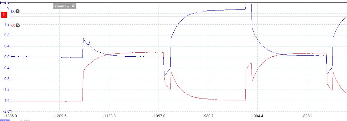
I've included a scope shot of the waveform output (this is feeding a piezo, thus the capacitive coupling). This is the same regardless of whether the TimerSynchronize is there or not.

TimerWaitOnTriggerControl also doesn't seem to be working.

driverlib.lib is included in the build.

EDIT: Formatting

    PWM_Params params;

    PWM_Params_init(&params);
    params.idleLevel = PWM_IDLE_LOW;
    params.dutyUnits = PWM_DUTY_US;
    params.dutyValue = BUZZER_PWM_DUTY_US;
    params.periodUnits = PWM_PERIOD_US;
    params.periodValue = BUZZER_PWM_PERIOD_US;
    pwm1 = PWM_open(BUZZER_I1_PWM, &params);
    if (pwm1 == NULL) {
        Log_debug(0, LOG_LEVEL_WARNING, "BUZZER PWM1 FAIL");
        return;
    }

    pwm2 = PWM_open(BUZZER_I2_PWM, &params);
    if (pwm2 == NULL) {
        Log_debug(0, LOG_LEVEL_WARNING, "BUZZER PWM2 FAIL");
        return;
    }

    TimerLevelControl(GPT2_BASE, TIMER_A, false);
    TimerLevelControl(GPT2_BASE, TIMER_B, true);

    PWM_start(pwm1);
    PWM_start(pwm2);

    // This doesn't seem to be working.
    TimerSynchronize(GPT0_BASE, TIMER_2A_SYNC || TIMER_2B_SYNC);
  • Hi Laur,
    That looks incredibly fascinating, and far away from PWM. Could you tell me more about your hardware (i.e. launchpads, wiring etc.) and software (i.e. BLE-Stack version etc) setup?
  • I should note that the output is measured on the piezo buzzer, not on the output legs of the MCU. So that's on the other side of the resistors from MCU. The waveform only demonstrates that the PWMs are not synchronized, and are otherwise quite expected. The red trace scale is not visible on the screenshot, but it is nicely settling on the expected 0 and 1.8 V.

    HW: Custom board, PWM outputs, drive strength high, 360K resistors to either leg of the buzzer. IO voltage 1.8 V.
    SDK: SimpleLink CC2640R2 SDK 3.10.00.15
  • Hi Laur,

    I assume you have seen this thread as well?
    e2e.ti.com/.../642986

    Could you share your PWM board file settings with me so I can see how the PWM is setup in your case?
  • First of all: I noticed the "||" where there ought to be "|" in TimerSynchronize. Fixing that didn't make a difference.

    Setup (LAUNCHXL naming remains):

    #include <ti/drivers/PWM.h>
    #include <ti/drivers/pwm/PWMTimerCC26XX.h>
    
    #define PWM_COUNT 4
    
    PWMTimerCC26XX_Object pwmtimerCC26xxObjects[PWM_COUNT];
    
    const PWMTimerCC26XX_HwAttrs pwmtimerCC26xxHWAttrs[PWM_COUNT] = {
    { .pwmPin = HW_PIN_OMTR_DRV_I1, .gpTimerUnit = CC2640R2_LAUNCHXL_GPTIMER1A },
    { .pwmPin = HW_PIN_OMTR_DRV_I2, .gpTimerUnit = CC2640R2_LAUNCHXL_GPTIMER1B },
    { .pwmPin = HW_PIN_OBUZZ_I1, .gpTimerUnit = CC2640R2_LAUNCHXL_GPTIMER2A },
    { .pwmPin = HW_PIN_OBUZZ_I2, .gpTimerUnit = CC2640R2_LAUNCHXL_GPTIMER2B },
    };
    
    const PWM_Config PWM_config[PWM_COUNT] = {
    { &PWMTimerCC26XX_fxnTable, &pwmtimerCC26xxObjects[CC2640R2_LAUNCHXL_PWM0], &pwmtimerCC26xxHWAttrs[CC2640R2_LAUNCHXL_PWM0] },
    { &PWMTimerCC26XX_fxnTable, &pwmtimerCC26xxObjects[CC2640R2_LAUNCHXL_PWM1], &pwmtimerCC26xxHWAttrs[CC2640R2_LAUNCHXL_PWM1] },
    { &PWMTimerCC26XX_fxnTable, &pwmtimerCC26xxObjects[CC2640R2_LAUNCHXL_PWM2], &pwmtimerCC26xxHWAttrs[CC2640R2_LAUNCHXL_PWM2] },
    { &PWMTimerCC26XX_fxnTable, &pwmtimerCC26xxObjects[CC2640R2_LAUNCHXL_PWM3], &pwmtimerCC26xxHWAttrs[CC2640R2_LAUNCHXL_PWM3] },
    };
    
    const uint_least8_t PWM_count = PWM_COUNT;


    //And in a separate header file
    
    #define BUZZER_I1_PWM CC2640R2_LAUNCHXL_PWM2
    #define BUZZER_I2_PWM CC2640R2_LAUNCHXL_PWM3

  • HI Laur,

    Looking at the code again I see that you set the GPTimer0 base for synchronization. As the PWM you define use the GPTimer2, you should also use this base for the sync call:

    TimerSynchronize(GPT0_BASE GPT2_BASE, TIMER_2A_SYNC | TIMER_2B_SYNC);

    Did you correct this as well on your side?

  • I tried it, and it didn't fix the issue. However, the documentation for TimerSynchronize explicitly states that one must use GPT0_BASE, and going to the source file in the SDK folder, it is even supposed to ASSERT that GPT0_BASE is used (as far as I can tell, the register is mirrored at all GPT blocks, but as it can synchronize across blocks, it shouldn't actually matter).

    That's another weird thing however: The assertion did not get triggered, when I used GPT2_BASE (though now I can't recall if I tried it on a debug build or not).

    Perhaps I'm missing something regarding the use of the Timer driver? Does it need any explicit initialization? Looking at the driver, it would seem to be a plain register access, with no preconditions.

  • Hi Laur,

    You are absolutely right, it slipped my mind but yes, you need to use the GPTimer0 base for synchronization. What this means in practice is that you also need to ensure that the GPTimer0 peripheral is powered and clocked when trying to synchronize the other timer blocks. Unless you are using GPTimer0 somewhere else in your application, i would not expect it to be powered when you run the PWM on GPTimer2 and thus it can't synchronize the timers for you.

    A way to verify if it is powered is to pause and try to access it using the register view.
  • Hum. I was sure I answered...

    I switched the piezo to use GPT0 (no point waking it up just to synchronize), and tried again. Still no dice, the waveform remains unchanged.

  • Hi Laur,

    I tested this out myself and have no issue getting the signals to sync using this small example:

    /*
     *  ======== mainThread ========
     *  Task periodically increments the PWM duty for the on board LED.
     */
    void *mainThread(void *arg0)
    {
        PWM_Handle pwm1 = NULL;
        PWM_Handle pwm2 = NULL;
        PWM_Handle pwm3 = NULL;
    
        PWM_Params params;
    
        /* Call driver init functions. */
        PWM_init();
    
        PWM_Params_init(&params);
        params.dutyUnits = PWM_DUTY_US;
        params.dutyValue = 1500;
        params.periodUnits = PWM_PERIOD_US;
        params.periodValue = 3000;
        
        /* Using GPTimer2 */
        pwm1 = PWM_open(Board_PWM0, &params);
        pwm3 = PWM_open(Board_PWM2, &params);
        /* Using GPTimer0 */
        pwm2 = PWM_open(Board_PWM1, &params);
        
        /* Enabled GPTimer0 */
        PWM_start(pwm3);
        
        /* Start GPTimer2 PWM signals out of sync with each other */
        PWM_start(pwm1);
        usleep(371);
        PWM_start(pwm2);
        
        /* Sync GPTimer2 PWM signals */
        TimerSynchronize(GPT0_BASE, TIMER_2A_SYNC | TIMER_2B_SYNC);
    
        PWM_setDuty(pwm1, 1000);
        usleep(487);
        PWM_setDuty(pwm2, 500);
    
        for (;;);
    
    }

    Could you try to simply run this example and verify that you can get it to work?