This thread has been locked.

If you have a related question, please click the "Ask a related question" button in the top right corner. The newly created question will be automatically linked to this question.

CC2640R2F: I2C hang and cannot recovery

Part Number: CC2640R2F
Other Parts Discussed in Thread: CC2640, , CC2544

Hi team,

Our customer use CC2640R2 to connect I2C slave device. Sometimes, CC2640R2 I2C will hang and cannot recovery.

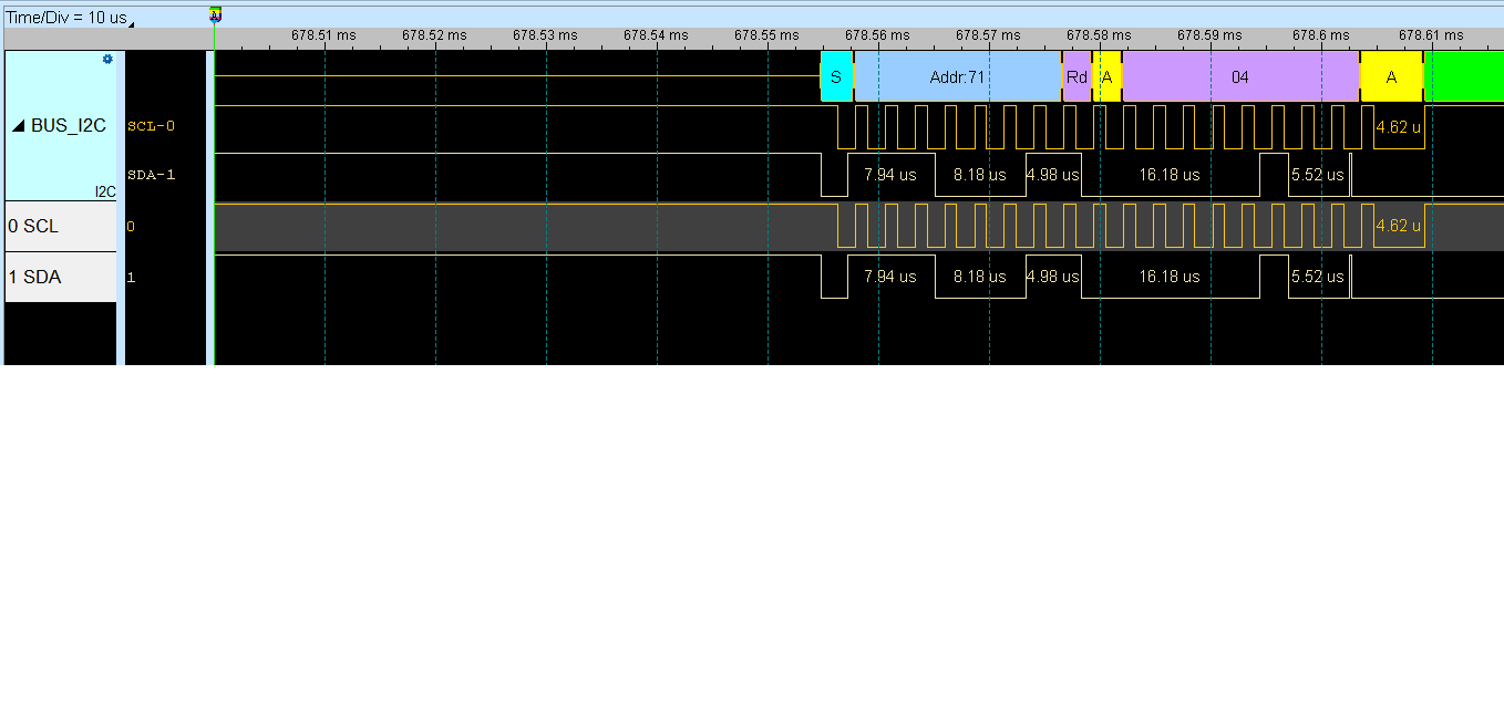
Below show the waveform when i2c transaction fail.

(1) The failure transaction is shown as below.

(2)  After the i2c transaction failure, cc2640 perform the i2c transfer and the waveform is shown as below.

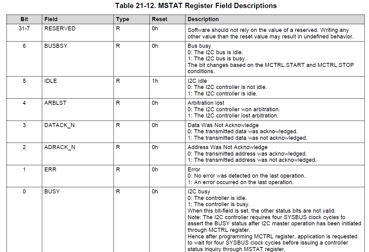
We found the MSTAT register (below Table) and the DATAACK_N bit keep to report 1.


May I know how to clear this bit by setting i2c regisgters? Thanks

  • Hi Jerry,

    What device is the CC2640R2F communicating with?
    Have you tried communicating with any other I2C devices?
    Which SDK are you using?
    What HW are you using?
    If custom HW, can you replicate on a LaunchPad?

    Regards,
    Fredrik
  • Hi team,

    What device is the CC2640R2F communicating with?
    --> keyboard IC

    Have you tried communicating with any other I2C devices?
    --> no. In this project, CC2640R2 is to get keyboard data and transmit to CC2544.

    Which SDK are you using?
    --> SDK V1.50. We find a known I2C issue on SDK V3.10. So we integrate the I2C driver from SDK V3.10 to customer’s code.

    What HW are you using?
    —> CC2640R2+keyboard IC

    If custom HW, can you replicate on a LaunchPad?
    —> not yet

    Please focus on why the MSTAT register and the DATAACK_N bit always keep to report 1 when we recovery I2C.
  • Hi Jerry,

    The register indicates that the data sent was not acknowledged. There is also a clock pulse missing during the ACK, so these are probably connected. Have you looked into why the clock pulse is missing? Is the slave doing clock stretching for some reason?

    Could it be that the signals are distorted somehow? What pull-up values are you using, and what I2C speed?

    I do not fully follow your explanation of what happens. In logic analyzer capture 1, the CC2640 is trying to write data to the keyboard IC, right? And the DATACK bit is set after the data byte has been transferred? What happens in the I2C driver code at this point?

    Regards,
    Fredrik
  • Have you looked into why the clock pulse is missing? Is the slave doing clock stretching for some reason?
    ==> I am not sue why the clock pulse is missing. The clock is generated by cc2640 and I2c hardware should generates 9 clocks when we perform the R/W operation on I2c registers.  From waveform,the signal keep high after 8 clocks so it's not stretching by slave.
     
    Could it be that the signals are distorted somehow? 
    What pull-up values are you using, and what I2C speed?
    ==> We capture the I2c waveform from LA during we do stress testing on I2c transaction. Therefore, we don't have the waveform from scope to make sure there is no distorted on I2c signals.
      For now, customer is using 1.5k for 400k I2c transaction.
      We have check the I2c signal quality and it looks good.
    I do not fully follow your explanation of what happens. In logic analyzer capture 1, the CC2640 is trying to write data to the keyboard IC, right? 
    ==> yes, cc2640 is trying to send 32 bytes but the signal is corrupt at writing the second byte to device.
    And the DATACK bit is set after the data byte has been transferred? 
    ==> yes, the DAYACK is always set after data byte has been transferred.
    What happens in the I2C driver code at this point? 
    ==> (a) Read error status (0x804) by API
           (b) Send the stop if the Error status is set.

    My point is that why the DATAACK always report "1". We have tried to send the all of commands (as below)to 0x804 Master control register by JTAG

    but the DAYACK Bit is always set.

    #define I2C_MASTER_CMD_BURST_RECEIVE_CONT   0x00000009

    Referenced by I2CMasterControl().

    #define I2C_MASTER_CMD_BURST_RECEIVE_ERROR_STOP   0x00000004

    Referenced by I2CMasterControl().

    #define I2C_MASTER_CMD_BURST_RECEIVE_FINISH   0x00000005

    Referenced by I2CMasterControl().

    #define I2C_MASTER_CMD_BURST_RECEIVE_START   0x0000000b

    Referenced by I2CMasterControl().

    #define I2C_MASTER_CMD_BURST_SEND_CONT   0x00000001

    Referenced by I2CMasterControl().

    #define I2C_MASTER_CMD_BURST_SEND_ERROR_STOP   0x00000004

  • Hi Jerry,

    The DATACK bit means that the data was not acknowledged by the slave. This is most likely connected to the missing clock pulse somehow.

    Can you try to change the datarate to 100 kbps and see if that changes anything?

    Regards,
    Fredrik
  • Hi Fredrik,

    Customer need high report rate. They cannot accept I2C of 100KHz. Is there any limitation on I2C with 400 KHz?

    Could you focus why that bit cannot be clear ?

  • Hi Jerry,

    You need to figure out why the data is not properly ACKed. Running at a lower clock speed may reveal whether there is an issue with the physical signals or not. It would also be good to test another I2C slave to see if the problem is related to the slave.

    Does the DATACK bit not clear when you run a new Start condition?

    Regards,
    Fredrik