This thread has been locked.

If you have a related question, please click the "Ask a related question" button in the top right corner. The newly created question will be automatically linked to this question.

CC2640R2F: AoA measurement Error

Part Number: CC2640R2F

Hi,

  We're conducting AoA measurements with our own Antenna instead of using BOOSTXL-AOA.

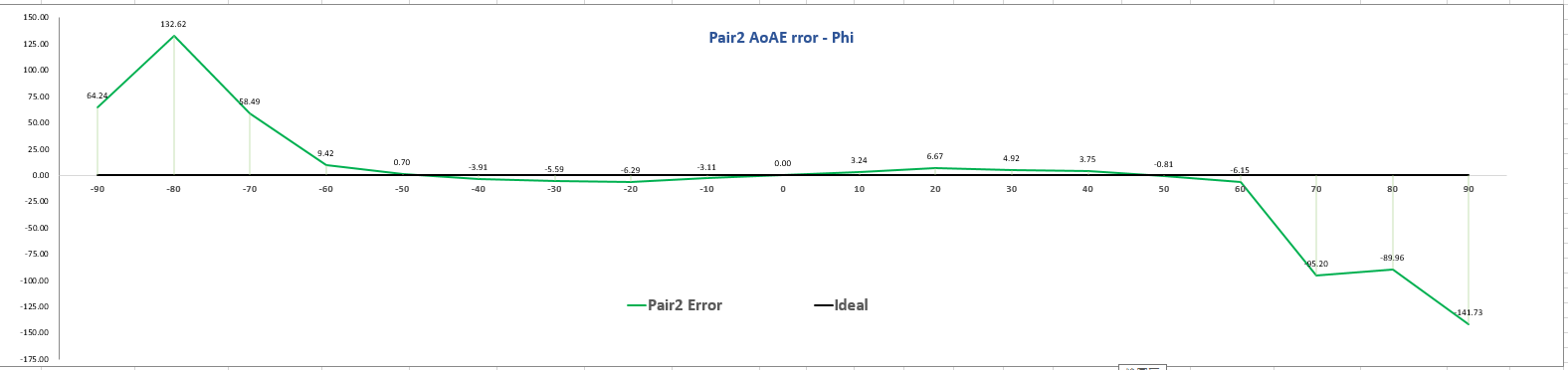
  It seems that comparing to TI's document (less than 10º of error until around ±80º), usable range of measured AoA with our Antenna is smaller ( -60~+60)

  1. What might be the cause of such measurement results, and how can we improve the effective AoA range?

  2. Regarding the AoA Error (±10º) within the effective range, what might be the major error sources (e.g. on board interference, gain, path delay, crystal inaccuracy, etc) that cause phase drift and so on?

      Is there any design guideline (RF layout, antenna, etc) to minimize the AoA Error ?

  Thanks~

  • Hi Aaron,
    I have reached out to our antenna expert for a comment. Would you be able to share your design?
  • Hi Aaron,

    The first thing I think that can cause this is that the distance between your antennas is too large. The distance between the antennas should be less than λ/2. If distance is larger than λ/2 (180°) you could see issues similar to what you shown in your graph.
    One other thing is antenna type. What antenna type are you using? Does it have a constant phase center?

    Best Regards,
    R.M
  • Hi Joakim, R.M,

       Thanks for the feedback.

       We're evaluating different antenna types (URA, UCA, etc), the posted AoA graph is the measurement result coming from simple URA (2x2), and the distance between antennas is λ/2 (6.25cm)

       The measurement setup between Tx and Rx is around 2m.

       Except the antenna distance, what might be the factor of such result ? ( does antenna pattern affect phase difference?)

       As for AoA accuracy within the usable angle range (-80º ~ +80º) ,

      what error sources (e.g. on board interference, Rx gain, path delay, crystal inaccuracy?) should be taken care on hardware to minimize the phase drift that cause AoA Error (±10º) ?

      Given that AoA accuracy is the key point that affect the application scenarios, we want to know how accurate it could be or there's inevitable error range based on the signal nature.

     Thanks~


  • Btw, we're using patch antenna instead of dipole antenna.
  • Hi Aaron,

    I think the main reason for these results are the distance between the antennas. I would use less than λ/2 to make sure you always get less than 180 degrees phase difference between the antenna. On the BOOSTXL-AoA evaluation board we use a distance between the antennas that is almost λ/4 to make sure we don't get this wrapping (occurs when phase difference is larger than 180 degrees). Keep in mind that electrical distance is typically less than physical distance.

    When it comes to other error sources Rx gain and crystal inaccuracy should not interfere as it would be the same for all antennas. Path delay could interfere if the delay is different from the respective antennas. Coupling between the antennas can interfere but this is tied to the distance between the antennas so this will be a trade-off between angle range and performance. Antenna pattern can interfere as this affect how each antenna electrically sees the environment around it. A patch in the middle will have an antenna on each side while a patch on one of the sides will only have on one or two sides. The size and shape of the ground plane underneath the patch antennas could/would also interfere.


    Best Regards,
    R.M
  • Hi R.M,
    Thanks for detailed explanation.