This thread has been locked.

If you have a related question, please click the "Ask a related question" button in the top right corner. The newly created question will be automatically linked to this question.

CC2640R2F: sleep mode current increases while using CAP array

Part Number: CC2640R2F


Hi,

I am using CC2640R2F as RC_OSC setting as we use internal RC as clock source.

We are using  simplelink_cc2640r2_sdk_2_30_00_28  SDK and host test as an example for end application. There is one of the test process Sleep mode current check we are using for production purpose so we have implemented customized command that will send from host to CC2640R2F to enter in sleep mode and we have used following two APIs to enter in sleep mode.

Power_releaseConstraint(PowerCC26XX_SB_DISALLOW);

Power_releaseConstraint(PowerCC26XX_IDLE_PD_DISALLOW);

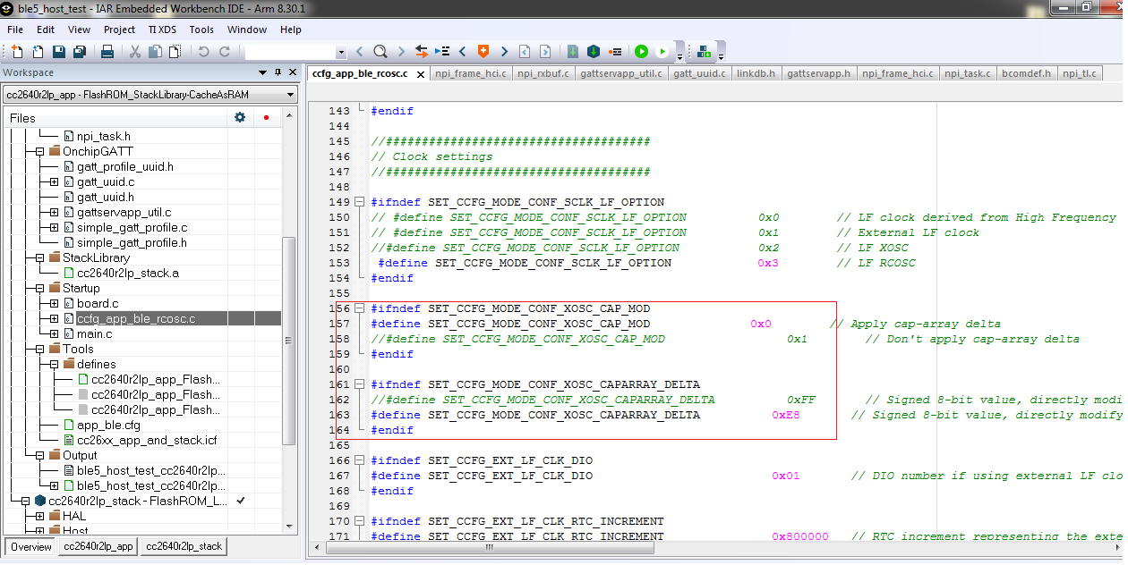
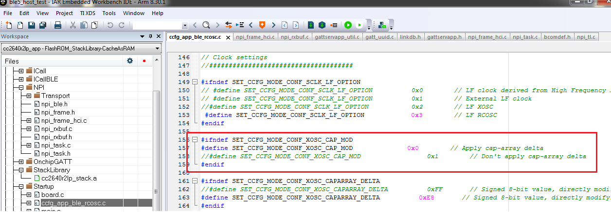
With this API  CC2640R2F enters in sleep mode and consumes approx 500uA current and its consistent for every device but one more test in production we use is crystal calibration and that is why we enable CAP array and writes some CAP array value according to remove frequency offset but issue is that once we enable CAP array sleep mode current increases to 3 times approx around 1.8mA from 500uA.

How to sort out this issue and what could be the problem? 


Regards,

Bhavin

  • Hi Bhavin,

    Assigning an expert to follow up asap.

  • Hi Bhavin,

    Host test will not go to standby mode because it's pending on incoming messages over UART or SPI. 

  • Hi Bhavin,

    Setting a new cap-array value will not change the current consumption. My guess is that something else is happening in your device when you change the setting. You also say that you are using the RC OSC, but the cap-array is only used with the crystal oscillator.

    Regards,
    Fredrik

  • Hi Marie,

    Yes agreed that it will not go fully in sleep mode but it should go partially and by practically it seems that current consumption goes down from approx 2 mA to 500uA and that is acceptable at this moment for us but when we enable cap array this 500uA current also not coming. 

    Regards,

    Bhavin

  • Hi Fredrik,

    Actually for our in house designed module we have not used external crystal and we are using internal RC_OSC.

    In SDK cap array enable or disable setting is available for RC_OSC setting. Kindly find the following screenshot.

    Regards,

    Bhavin

  • Hi Bhavin,

    CCFG fields are fixed, all options are always available. Anyway, based on the screenshot, I assume you mean that you are talking about the low frequency (32 kHz) clock. You are still using a 24 MHz crystal, right?

    The cap-array is used to tune the 24 MHz crystal oscillator, it has nothing to do with the LF clock. More details about crystal tuning can be found in www.ti.com/lit/pdf/swra640 

  • Hi Fredrik,

    Yes agreed what you have written.

    We are using 24MHz crystal and not using 32KHz.

    But the issue is current increases while using Cap array in sleep mode.

    Regards,

    Bhavin

  • Hi Bahvin,

    As I wrote earlier, adjusting the cap-array does not impact current consumption. 

    It could be that your 500 uA mode is with the crystal oscillator disabled. If you are enabling the crystal oscillator after changing the cap-array setting and forcing it on, it will block the device from entering Standby.

    You can easily verify that cap-array does not affect current consumption with our pinStandby SW example.

    Regards,
    Fredrik

  • Hi Fredrik,

    Crystal Oscillator enable/disable means cap array enable disable you are talking about ?

    As per following screenshot.

    Regards,

    Bhavin

  • Hi Bhavin,

    No, I mean whether the actual crystal oscillator is running or not. 

    Regards,
    Fredrik

  • Hi Fredrik,

    We are using 24 MHz crystal as it is mandatory for RF.

    We are not using 32 KHz crystal used for RTC as well MCU but we are not using RTC and we can drive MCU through internal RC.

    I just wanted to modified host test(SDK simplelink_cc2640r2_sdk_2_30_00_28) example earlier which was configured as cache_as_RAM and used ble module with external 32 KHz crystal but now for module without 32 KHz still want to used cache_as _RAM but with internal RC.

    So instead of selecting direct RC_OSC configuration i just modified already used cache_as_RAM setting to internal RC as per following steps listed in doc

    Using 32-kHz Crystal-Less Mode

    BLE5-Stack 1.01.03.00 includes support for operating the CC2640R2 in a 32-kHz crystal-less mode for peripheral and broadcaster (beacon) role configurations. By using the internal low-frequency RC oscillator (RCOSC_LF), the 32-kHz crystal can be removed from the board layout.

    There are a few steps that must be taken to enable this feature. For any peripheral project, the following change is required for IAR. For CCS user, please see the Running Bluetooth Low Energy on CC2640 Without 32 kHz Crystal for the needed steps to enable RCOSC_LF in your project. You will find more detail regarding this feature in the aforementioned application note.

    1. Include `rcosc_calibration.c, rcosc_calibration.h and ccfg_app_ble_rcosc.c files which locate at <SDK_INSTALL_DIR>\source\ti\ble5stack\common\cc26xx\rcosc

    2. Exclude ccfg_app_ble.c from build.

    3. Add USE_RCOSC to the .opt file containing the application defines.

    4. Add the following code to your peripheral project.c

      Listing 109. RCOSC calibration include
      #ifdef USE_RCOSC
      #include "rcosc_calibration.h"
      #endif //USE_RCOSC
      
    5. Add the following code to your peripheralproject_init function in peripheral project.c

      Listing 110. RCOSC calibration enable
      #ifdef USE_RCOSC
      RCOSC_enableCalibration();
      #endif // USE_RCOSC
      
    6. If using a custom board file, enable the RCOSC in the power policy. The board files included with the BLE5-Stack:

      Listing 111. Power driver configuration
      PowerCC26X2_Config PowerCC26X2_config = {
        .policyInitFxn     = NULL,
        .policyFxn         = &PowerCC26XX_standbyPolicy,
        .calibrateFxn      = &PowerCC26XX_calibrate,
        .enablePolicy      = TRUE,
        .calibrateRCOSC_LF = TRUE,
        .calibrateRCOSC_HF = TRUE,
      };
      
    7. Constrain the temperature variation to be less than 1°C/sec. If the temperature is to change faster than 1°C/sec, then a short calibration interval must be used. Calibration interval can be tuned in rcosc_calibration.h

      Listing 112. RCOSCLF calibration interval
      // 1000 ms
      #define RCOSC_CALIBRATION_PERIOD   1000
      

    Note

    Use of the internal RCOSC_LF requires a sleep clock accuracy (SCA) of 500 ppm.

    And one more setting as per following.

    Regards,

    Bhavin

  • Hi Bhavin,

    I believe this approach is fine, but I will let Marie verify.

    The 32k clock configuration is not related to the cap-array or the 24 MHz crystal oscillator though. I believe the root cause of the current consumption you are observing has to do with trying to get HostTest into Standby, and how the oscillator is configured when you do the CapArray adjustment. 500 uA is not expected current consumption in any power mode, neither is 1500 uA. As such, you need to figure out what states the IC is placed in by your SW. 

    Adjusting the CapArray in itself does not affect current consumption. As I have already mentioned, you can easily verify this with a simple example, such as PinStandby.

    Regards,
    Fredrik

  • Hi Fredrik,

    Okay. 

    Please confirm above is correct implementation or not ?

    Regards,

    Bhavin

  • Hi Bhavin,

    If you followed all the steps in the app note that you have posted the software configuration should be fine.

    As Fredrik says, the 32k clock configuration is not related to the cap-array or the 24 MHz crystal oscillator though. I believe the root cause of the current consumption you are observing has to do with trying to get HostTest into Standby, and how the oscillator is configured when you do the CapArray adjustment. 500 uA is not expected current consumption in any power mode, neither is 1500 uA. As such, you need to figure out what states the IC is placed in by your SW.