This thread has been locked.

If you have a related question, please click the "Ask a related question" button in the top right corner. The newly created question will be automatically linked to this question.

CC2640R2F: Handling of Crystal Frequency Tolerance

Part Number: CC2640R2F
Other Parts Discussed in Thread: SYSBIOS

In our application.  we use “OSC_XOSC_LF” as Low Frequency Source. Crystal used is Epson FC-135.

From datasheet it is known that, Crystal Epson FC-135 has an error tolerance of +- 20 ppm.

My question is how this error tolerance is corrected by upscaling /downscaling and fed to RTC.

Is it taken care in stack itself or should we take care of it in application.

If done in stack, where can I find it ?


Thanks,

Aarthi

  • I have gone through this already. HCI_EXT_SetSCACmd() API is mainly used to set sleep clock accuracy which is necessary for Bluetooth connection.

    I wanted to know RTC accuracy in CC2640R2F when OSC_XOSC_LF is selected as Low frequency source and also I have set 200 ppm as sleep clock source accuracy using HCI_EXT_SetSCACmd().

    It is expected to have clock drift because of crystal frequency tolerance. How much drift is expected to have according to my values? And,  How this drift is handled in TIRTOS timers? Can you kindly explain this is detail?

  • The xtal is the reference and everything internally will have this accuracy or worse (for the RC oscillator) 

    If you have a xtal with +/- 40 ppm this will then mean that you will wake up from a low power mode with +/- 40 ppm accuracy. This is taken into account be the stack by using HCI_EXT_SetSCACmd(). Then the chip knows which accuracy that is used on the reference and can account for this be adding the required margin when to going up from sleep. If you have set the accuracy to 200 ppm and use a 20 ppm clock you will increase the power consumption more than you have to since you force the system to wake up before it have to since your xtal is much more accurate than you set as the sleep clock accuracy. 

  • Thanks for the explanation.

    Can you also please explain me how much clock drift is expected for the mentioned values.

    Since the crystal frequency tolerance is 20ppm , is the clock drift expected for RTOS timers 20us?

    Or as sleep clock accuracy is set to 200ppm, is the clock drift expected for RTOS timers 200us?

  • From the below post link,

    https://e2e.ti.com/support/legacy_forums/embedded/tirtos/f/355/t/564127

    I understand that there will be some slight error in the accuracy of actual tick but it does not accumulate over time as it will be dynamically computed and adjusted.

    I wanted to know how this dynamic calibration works. Can you kindly let me know which module takes care of doing that, so that I can get deep insight into it.

  • You link to a post that no longer exist?

  • You can find the details in the TI-RTOS implementation in the source code. for this particular question you can look into kernel\tirtos\packages\ti\sysbios\knl\clock.c ( Clock_workFunc etc) 

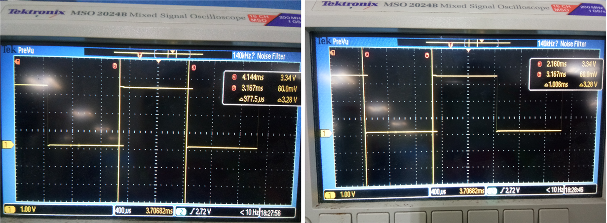
  • In my application, I'm running a periodic clock of 1 ms timeout continuously. For each timeout, I toggle a GPIO pin and I have traced the output in Logic Analyzer.

    I see that Timeout value is always not the same. Sometimes it is 1.007ms, in some cases it is 0.9765ms.

    Since I'm using crystal EPSON FC135 for RTC, I expect  ~20uS deviation at room temperature.. But this is nowhere matching with the logic analyzer output. Can you shed some light why we see 1.007ms/0.9765ms for 1ms Timeout. ?

    If suppose, this additional delay happened because of Gpio toggling, it should be constant all the time. But its not happening so.

    I see, the periodicity always follows a pattern.

    T0 - 1.007 ms

    T1 - 1.007 ms

    T2 - 1.007 ms

    T3 - 1.007 ms

    T4 - 0.9765 ms

    T5 - 1.007ms

    T6 - 1.007ms

    T7 - 1.007ms

    T8 - 0.9765ms

    T9 - 1.007ms

    T10 - 1.007ms

    T11 - 1.007ms

    T12 - 0.9765ms

    and again this sequence repeats.

    Kindly detail me with reply why we see this behavior.

    If some calibration done in software, can you detail me how this calibration works.

  • Do you have the full code? I would suspect that you get a variation due to how TI-RTOS works, in other words when the setting of the DIO is scheduled. It's not given that the DIO is set at the same time every time even if the clock fires with exactly the same interval.

  • bool toggle= TRUE;
    
    
    void Clock_configure(void)  
    
    {
    
        GPIOPinHandle = PIN_open(&GPIOPinState,  GPIOPinList);
    
        Clock_Params clockParams;
        Clock_Params_init(&clockParams); /*Setup parameters*/
        clockParams.startFlag = TRUE;
        clockParams.arg= NULL;
        clockParams.period=((1) * 1000) / Clock_tickPeriod;
    
        Clock_construct(&periodicClock, ClockHandler, ((1) * 1000) / Clock_tickPeriod, &clockParams);
    
    }
    
    
    void ClockHandler(xdc_UArg arg)
    {
        toggle=!toggle;
        PIN_setOutputValue(GPIOPinHandle, IOID_2, toggle);
    }

  • Btw, before I look into the code, are you sure you are measuring this correctly? I have had issues before with limited samplings rate on the logic analyzator, have you calculated the error you will have with the settings you are using? 

  • I haven't calculated the error.

    But I have cross verified the results using an oscilloscope.

    I have attached the screenshots. Kindly have a look.

  • Do you have the full project since not all variables are defined in the code snippet you pasted in.

  • I'm using simplelink_cc2640r2_sdk_1_40_00_45 and xdctools_3_50_02_20_core packages.

    I have modified simple_peripheral example application to simulate the same output.

    Attaching main.c file which contains the full project of what I stated in previous comments(GPIO toggling for 1ms timeout)

    /******************************************************************************
    
     @file       main.c
    
     @brief main entry of the BLE stack sample application.
    
     Group: CMCU, SCS
     Target Device: CC2640R2
    
     ******************************************************************************
     
     Copyright (c) 2013-2017, Texas Instruments Incorporated
     All rights reserved.
    
     Redistribution and use in source and binary forms, with or without
     modification, are permitted provided that the following conditions
     are met:
    
     *  Redistributions of source code must retain the above copyright
        notice, this list of conditions and the following disclaimer.
    
     *  Redistributions in binary form must reproduce the above copyright
        notice, this list of conditions and the following disclaimer in the
        documentation and/or other materials provided with the distribution.
    
     *  Neither the name of Texas Instruments Incorporated nor the names of
        its contributors may be used to endorse or promote products derived
        from this software without specific prior written permission.
    
     THIS SOFTWARE IS PROVIDED BY THE COPYRIGHT HOLDERS AND CONTRIBUTORS "AS IS"
     AND ANY EXPRESS OR IMPLIED WARRANTIES, INCLUDING, BUT NOT LIMITED TO,
     THE IMPLIED WARRANTIES OF MERCHANTABILITY AND FITNESS FOR A PARTICULAR
     PURPOSE ARE DISCLAIMED. IN NO EVENT SHALL THE COPYRIGHT OWNER OR
     CONTRIBUTORS BE LIABLE FOR ANY DIRECT, INDIRECT, INCIDENTAL, SPECIAL,
     EXEMPLARY, OR CONSEQUENTIAL DAMAGES (INCLUDING, BUT NOT LIMITED TO,
     PROCUREMENT OF SUBSTITUTE GOODS OR SERVICES; LOSS OF USE, DATA, OR PROFITS;
     OR BUSINESS INTERRUPTION) HOWEVER CAUSED AND ON ANY THEORY OF LIABILITY,
     WHETHER IN CONTRACT, STRICT LIABILITY, OR TORT (INCLUDING NEGLIGENCE OR
     OTHERWISE) ARISING IN ANY WAY OUT OF THE USE OF THIS SOFTWARE,
     EVEN IF ADVISED OF THE POSSIBILITY OF SUCH DAMAGE.
    
     ******************************************************************************
     Release Name: simplelink_cc2640r2_sdk_1_40_00_45
     Release Date: 2017-07-20 17:16:59
     *****************************************************************************/
    
    /*******************************************************************************
     * INCLUDES
     */
    
    #include <xdc/runtime/Error.h>
    
    #include <ti/drivers/Power.h>
    #include <ti/drivers/power/PowerCC26XX.h>
    #include <ti/sysbios/BIOS.h>
    #include <ti/sysbios/knl/Clock.h>
    #include <ti/display/Display.h>
    
    #include <icall.h>
    #include "hal_assert.h"
    #include "bcomdef.h"
    #include "peripheral.h"
    #include "simple_peripheral.h"
    
    /* Header files required to enable instruction fetch cache */
    #include <inc/hw_memmap.h>
    #include <driverlib/vims.h>
    
    #ifndef USE_DEFAULT_USER_CFG
    
    #include "ble_user_config.h"
    
    // BLE user defined configuration
    #ifdef ICALL_JT
    icall_userCfg_t user0Cfg = BLE_USER_CFG;
    #else  /* ! ICALL_JT */
    bleUserCfg_t user0Cfg = BLE_USER_CFG;
    #endif /* ICALL_JT */
    
    #endif // USE_DEFAULT_USER_CFG
    
    #ifdef USE_FPGA
    #include <inc/hw_prcm.h>
    #endif // USE_FPGA
    
    #define TEST_PIN IOID_2
    static const PIN_Config GPIOPinList[] = { (TEST_PIN | PIN_INPUT_DIS | PIN_GPIO_OUTPUT_EN |  PIN_GPIO_HIGH | PIN_PUSHPULL | PIN_DRVSTR_MAX), PIN_TERMINATE };
    static PIN_Handle GPIOPinHandle;
    static PIN_State GPIOPinState;
    static Clock_Struct periodicClock; /**< Timer handles for Periodic measurements */
    volatile bool toggle = TRUE;
    
    static void App_init(void);
    
    /*******************************************************************************
     * MACROS
     */
    
    /*******************************************************************************
     * CONSTANTS
     */
    
    #if defined( USE_FPGA )
      #define RFC_MODE_BLE                 PRCM_RFCMODESEL_CURR_MODE1
      #define RFC_MODE_ANT                 PRCM_RFCMODESEL_CURR_MODE4
      #define RFC_MODE_EVERYTHING_BUT_ANT  PRCM_RFCMODESEL_CURR_MODE5
      #define RFC_MODE_EVERYTHING          PRCM_RFCMODESEL_CURR_MODE6
      //
      #define SET_RFC_BLE_MODE(mode) HWREG( PRCM_BASE + PRCM_O_RFCMODESEL ) = (mode)
    #endif // USE_FPGA
    
    /*******************************************************************************
     * TYPEDEFS
     */
    
    /*******************************************************************************
     * LOCAL VARIABLES
     */
    
    /*******************************************************************************
     * GLOBAL VARIABLES
     */
    
    #ifdef CC1350_LAUNCHXL
    #ifdef POWER_SAVING
    // Power Notify Object for wake-up callbacks
    Power_NotifyObj rFSwitchPowerNotifyObj;
    static uint8_t rFSwitchNotifyCb(uint8_t eventType, uint32_t *eventArg,
                                    uint32_t *clientArg);
    #endif //POWER_SAVING
    
    PIN_State  radCtrlState;
    PIN_Config radCtrlCfg[] =
    {
      Board_DIO1_RFSW   | PIN_GPIO_OUTPUT_EN | PIN_GPIO_LOW  | PIN_PUSHPULL | PIN_DRVSTR_MAX, /* RF SW Switch defaults to 2.4GHz path*/
      Board_DIO30_SWPWR | PIN_GPIO_OUTPUT_EN | PIN_GPIO_HIGH | PIN_PUSHPULL | PIN_DRVSTR_MAX, /* Power to the RF Switch */
      PIN_TERMINATE
    };
    PIN_Handle radCtrlHandle;
    #endif //CC1350_LAUNCHXL
    
    /*******************************************************************************
     * EXTERNS
     */
    
    extern void AssertHandler(uint8 assertCause, uint8 assertSubcause);
    
    extern Display_Handle dispHandle;
    
    /*******************************************************************************
     * @fn          Main
     *
     * @brief       Application Main
     *
     * input parameters
     *
     * @param       None.
     *
     * output parameters
     *
     * @param       None.
     *
     * @return      None.
     */
    int main()
    {
    #if defined( USE_FPGA )
      HWREG(PRCM_BASE + PRCM_O_PDCTL0) &= ~PRCM_PDCTL0_RFC_ON;
      HWREG(PRCM_BASE + PRCM_O_PDCTL1) &= ~PRCM_PDCTL1_RFC_ON;
    #endif // USE_FPGA
    
      /* Register Application callback to trap asserts raised in the Stack */
      RegisterAssertCback(AssertHandler);
    
      PIN_init(GPIOPinList);
    
    #ifdef CC1350_LAUNCHXL
      // Enable 2.4GHz Radio
      radCtrlHandle = PIN_open(&radCtrlState, radCtrlCfg);
    
    #ifdef POWER_SAVING
      Power_registerNotify(&rFSwitchPowerNotifyObj,
                           PowerCC26XX_ENTERING_STANDBY | PowerCC26XX_AWAKE_STANDBY,
                           (Power_NotifyFxn) rFSwitchNotifyCb, NULL);
    #endif //POWER_SAVING
    #endif //CC1350_LAUNCHXL
    
    #if defined( USE_FPGA )
      // set RFC mode to support BLE
      // Note: This must be done before the RF Core is released from reset!
      SET_RFC_BLE_MODE(RFC_MODE_BLE);
    #endif // USE_FPGA
    
    #ifdef CACHE_AS_RAM
      // retain cache during standby
      Power_setConstraint(PowerCC26XX_SB_VIMS_CACHE_RETAIN);
      Power_setConstraint(PowerCC26XX_NEED_FLASH_IN_IDLE);
    #else
      // Enable iCache prefetching
      VIMSConfigure(VIMS_BASE, TRUE, TRUE);
      // Enable cache
      VIMSModeSet(VIMS_BASE, VIMS_MODE_ENABLED);
    #endif //CACHE_AS_RAM
    
    #if !defined( POWER_SAVING ) || defined( USE_FPGA )
      /* Set constraints for Standby, powerdown and idle mode */
      // PowerCC26XX_SB_DISALLOW may be redundant
      Power_setConstraint(PowerCC26XX_SB_DISALLOW);
      Power_setConstraint(PowerCC26XX_IDLE_PD_DISALLOW);
    #endif // POWER_SAVING | USE_FPGA
    
    #ifdef ICALL_JT
      /* Update User Configuration of the stack */
      user0Cfg.appServiceInfo->timerTickPeriod = Clock_tickPeriod;
      user0Cfg.appServiceInfo->timerMaxMillisecond  = ICall_getMaxMSecs();
    #endif  /* ICALL_JT */
      /* Initialize ICall module */
      ICall_init();
    
      /* Start tasks of external images - Priority 5 */
      ICall_createRemoteTasks();
    //
    //  /* Kick off profile - Priority 3 */
    //  GAPRole_createTask();
    //
    // SimpleBLEPeripheral_createTask();
    
      App_init();
    
      /* enable interrupts and start SYS/BIOS */
      BIOS_start();
    
      return 0;
    }
    
    
    static void ClockHandler(xdc_UArg arg)
    {
      toggle=!toggle;
      PIN_setOutputValue(GPIOPinHandle, TEST_PIN, toggle);
    }
    
    static void App_init(void)
    {
      
      GPIOPinHandle = PIN_open(&GPIOPinState, GPIOPinList);
      
      Clock_Params clockParams;
      Clock_Params_init(&clockParams); /*Setup parameters*/
      clockParams.startFlag = TRUE;
      clockParams.arg= NULL;
      clockParams.period=((1) * 1000) / Clock_tickPeriod;
    
      Clock_construct(&periodicClock, ClockHandler, ((1) * 1000) / Clock_tickPeriod, &clockParams);
    }
    
    /*******************************************************************************
     * @fn          AssertHandler
     *
     * @brief       This is the Application's callback handler for asserts raised
     *              in the stack.  When EXT_HAL_ASSERT is defined in the Stack
     *              project this function will be called when an assert is raised,
     *              and can be used to observe or trap a violation from expected
     *              behavior.
     *
     *              As an example, for Heap allocation failures the Stack will raise
     *              HAL_ASSERT_CAUSE_OUT_OF_MEMORY as the assertCause and
     *              HAL_ASSERT_SUBCAUSE_NONE as the assertSubcause.  An application
     *              developer could trap any malloc failure on the stack by calling
     *              HAL_ASSERT_SPINLOCK under the matching case.
     *
     *              An application developer is encouraged to extend this function
     *              for use by their own application.  To do this, add hal_assert.c
     *              to your project workspace, the path to hal_assert.h (this can
     *              be found on the stack side). Asserts are raised by including
     *              hal_assert.h and using macro HAL_ASSERT(cause) to raise an
     *              assert with argument assertCause.  the assertSubcause may be
     *              optionally set by macro HAL_ASSERT_SET_SUBCAUSE(subCause) prior
     *              to asserting the cause it describes. More information is
     *              available in hal_assert.h.
     *
     * input parameters
     *
     * @param       assertCause    - Assert cause as defined in hal_assert.h.
     * @param       assertSubcause - Optional assert subcause (see hal_assert.h).
     *
     * output parameters
     *
     * @param       None.
     *
     * @return      None.
     */
    void AssertHandler(uint8 assertCause, uint8 assertSubcause)
    {
    #if !defined(Display_DISABLE_ALL)
      // Open the display if the app has not already done so
      if ( !dispHandle )
      {
        dispHandle = Display_open(Display_Type_LCD, NULL);
      }
    
      Display_print0(dispHandle, 0, 0, ">>>STACK ASSERT");
    #endif // ! Display_DISABLE_ALL
    
      // check the assert cause
      switch (assertCause)
      {
        case HAL_ASSERT_CAUSE_OUT_OF_MEMORY:
    #if !defined(Display_DISABLE_ALL)
          Display_print0(dispHandle, 0, 0, "***ERROR***");
          Display_print0(dispHandle, 2, 0, ">> OUT OF MEMORY!");
    #endif // ! Display_DISABLE_ALL
          break;
    
        case HAL_ASSERT_CAUSE_INTERNAL_ERROR:
          // check the subcause
          if (assertSubcause == HAL_ASSERT_SUBCAUSE_FW_INERNAL_ERROR)
          {
    #if !defined(Display_DISABLE_ALL)
            Display_print0(dispHandle, 0, 0, "***ERROR***");
            Display_print0(dispHandle, 2, 0, ">> INTERNAL FW ERROR!");
    #endif // ! Display_DISABLE_ALL
          }
          else
          {
    #if !defined(Display_DISABLE_ALL)
            Display_print0(dispHandle, 0, 0, "***ERROR***");
            Display_print0(dispHandle, 2, 0, ">> INTERNAL ERROR!");
    #endif // ! Display_DISABLE_ALL
          }
          break;
    
        case HAL_ASSERT_CAUSE_ICALL_ABORT:
    #if !defined(Display_DISABLE_ALL)
          Display_print0(dispHandle, 0, 0, "***ERROR***");
          Display_print0(dispHandle, 2, 0, ">> ICALL ABORT!");
    #endif // ! Display_DISABLE_ALL
          HAL_ASSERT_SPINLOCK;
          break;
    
        case HAL_ASSERT_CAUSE_ICALL_TIMEOUT:
    #if !defined(Display_DISABLE_ALL)
          Display_print0(dispHandle, 0, 0, "***ERROR***");
          Display_print0(dispHandle, 2, 0, ">> ICALL TIMEOUT!");
    #endif // ! Display_DISABLE_ALL
          HAL_ASSERT_SPINLOCK;
          break;
    
        case HAL_ASSERT_CAUSE_WRONG_API_CALL:
    #if !defined(Display_DISABLE_ALL)
          Display_print0(dispHandle, 0, 0, "***ERROR***");
          Display_print0(dispHandle, 2, 0, ">> WRONG API CALL!");
    #endif // ! Display_DISABLE_ALL
          HAL_ASSERT_SPINLOCK;
          break;
    
      default:
    #if !defined(Display_DISABLE_ALL)
          Display_print0(dispHandle, 0, 0, "***ERROR***");
          Display_print0(dispHandle, 2, 0, ">> DEFAULT SPINLOCK!");
    #endif // ! Display_DISABLE_ALL
          HAL_ASSERT_SPINLOCK;
      }
    
      return;
    }
    
    
    /*******************************************************************************
     * @fn          smallErrorHook
     *
     * @brief       Error handler to be hooked into TI-RTOS.
     *
     * input parameters
     *
     * @param       eb - Pointer to Error Block.
     *
     * output parameters
     *
     * @param       None.
     *
     * @return      None.
     */
    void smallErrorHook(Error_Block *eb)
    {
      for (;;);
    }
    
    #if defined (CC1350_LAUNCHXL) && defined (POWER_SAVING)
    /*******************************************************************************
     * @fn          rFSwitchNotifyCb
     *
     * @brief       Power driver callback to toggle RF switch on Power state
     *              transitions.
     *
     * input parameters
     *
     * @param   eventType - The state change.
     * @param   eventArg  - Not used.
     * @param   clientArg - Not used.
     *
     * @return  Power_NOTIFYDONE to indicate success.
     */
    static uint8_t rFSwitchNotifyCb(uint8_t eventType, uint32_t *eventArg,
                                    uint32_t *clientArg)
    {
      if (eventType == PowerCC26XX_ENTERING_STANDBY)
      {
        // Power down RF Switch
        PIN_setOutputValue(radCtrlHandle, Board_DIO30_SWPWR, 0);
      }
      else if (eventType == PowerCC26XX_AWAKE_STANDBY)
      {
        // Power up RF Switch
        PIN_setOutputValue(radCtrlHandle, Board_DIO30_SWPWR, 1);
      }
    
      // Notification handled successfully
      return Power_NOTIFYDONE;
    }
    #endif //CC1350_LAUNCHXL || POWER_SAVING
    
    
    /*******************************************************************************
     */
    

    Fyi, I have disabled Gaprole and BLE tasks as I dont need them.

    You need to replace main.c file, and trace IOID_2 output in logic analyzer/oscilloscope.

  • - Any reason why you are using a fairly old SDK?

    - Have you tried to do this based on the empty example? Not sure how the stack impact the timing.

  • - It is quite old project which uses the SDK version what I mentioned in previous comments.

    Can you ensure that these delays wont be seen, if we use latest SDK.?

    - Yes, I have tried to run below code alone in main. But still I see same behaviour with timings

    #define TEST_PIN IOID_2
    static const PIN_Config GPIOPinList[] = { (TEST_PIN | PIN_INPUT_DIS | PIN_GPIO_OUTPUT_EN |  PIN_GPIO_HIGH | PIN_PUSHPULL | PIN_DRVSTR_MAX), PIN_TERMINATE };
    static PIN_Handle GPIOPinHandle;
    static PIN_State GPIOPinState;
    static Clock_Struct periodicClock; /**< Timer handles for Periodic measurements */
    volatile bool toggle = TRUE;
    
    static void App_init(void);
    
    int main()
    {
      PIN_init(GPIOPinList);
    
      App_init();
    
      /* enable interrupts and start SYS/BIOS */
      BIOS_start();
    
      return 0;
    }
    
    static void ClockHandler(xdc_UArg arg)
    {
      toggle=!toggle;
      PIN_setOutputValue(GPIOPinHandle, TEST_PIN, toggle);
    }
    
    static void App_init(void)
    {
      
      GPIOPinHandle = PIN_open(&GPIOPinState, GPIOPinList);
      
      Clock_Params clockParams;
      Clock_Params_init(&clockParams); /*Setup parameters*/
      clockParams.startFlag = TRUE;
      clockParams.arg= NULL;
      clockParams.period=((1) * 1000) / Clock_tickPeriod;
    
      Clock_construct(&periodicClock, ClockHandler, ((1) * 1000) / Clock_tickPeriod, &clockParams);
    }

  • - Any updates on this issue?

  • I would like to test with the code you are running but so far you have not provided me with a code that it's easy for me to test with. I would like have a full project that I can compile out of the box or a file that I can insert into a existing example and it will compile. I  don't want to use time to add required header files etc. 

  • As I said earlier, Im using simplelink_cc2640r2_sdk_1_40_00_45 and xdctools_3_50_02_20_core packages.

    In simple_peripheral example project (simplelink_cc2640r2_sdk_1_40_00_45\examples\rtos\CC2640R2_LAUNCHXL\blestack\simple_peripheral), kindly replace the main.c file (path: simplelink_cc2640r2_sdk_1_40_00_45\examples\rtos\CC2640R2_LAUNCHXL\blestack\simple_peripheral\src\app\main.c)  with the file I have attached below.

    /******************************************************************************
    
     @file       main.c
    
     @brief main entry of the BLE stack sample application.
    
     Group: CMCU, SCS
     Target Device: CC2640R2
    
     ******************************************************************************
     
     Copyright (c) 2013-2017, Texas Instruments Incorporated
     All rights reserved.
    
     Redistribution and use in source and binary forms, with or without
     modification, are permitted provided that the following conditions
     are met:
    
     *  Redistributions of source code must retain the above copyright
        notice, this list of conditions and the following disclaimer.
    
     *  Redistributions in binary form must reproduce the above copyright
        notice, this list of conditions and the following disclaimer in the
        documentation and/or other materials provided with the distribution.
    
     *  Neither the name of Texas Instruments Incorporated nor the names of
        its contributors may be used to endorse or promote products derived
        from this software without specific prior written permission.
    
     THIS SOFTWARE IS PROVIDED BY THE COPYRIGHT HOLDERS AND CONTRIBUTORS "AS IS"
     AND ANY EXPRESS OR IMPLIED WARRANTIES, INCLUDING, BUT NOT LIMITED TO,
     THE IMPLIED WARRANTIES OF MERCHANTABILITY AND FITNESS FOR A PARTICULAR
     PURPOSE ARE DISCLAIMED. IN NO EVENT SHALL THE COPYRIGHT OWNER OR
     CONTRIBUTORS BE LIABLE FOR ANY DIRECT, INDIRECT, INCIDENTAL, SPECIAL,
     EXEMPLARY, OR CONSEQUENTIAL DAMAGES (INCLUDING, BUT NOT LIMITED TO,
     PROCUREMENT OF SUBSTITUTE GOODS OR SERVICES; LOSS OF USE, DATA, OR PROFITS;
     OR BUSINESS INTERRUPTION) HOWEVER CAUSED AND ON ANY THEORY OF LIABILITY,
     WHETHER IN CONTRACT, STRICT LIABILITY, OR TORT (INCLUDING NEGLIGENCE OR
     OTHERWISE) ARISING IN ANY WAY OUT OF THE USE OF THIS SOFTWARE,
     EVEN IF ADVISED OF THE POSSIBILITY OF SUCH DAMAGE.
    
     ******************************************************************************
     Release Name: simplelink_cc2640r2_sdk_1_40_00_45
     Release Date: 2017-07-20 17:16:59
     *****************************************************************************/
    
    #include <ti/sysbios/BIOS.h>
    #include <ti/sysbios/knl/Clock.h>
    
    #include "board.h"
    
    
    #define TEST_PIN IOID_2
    static const PIN_Config GPIOPinList[] = { (TEST_PIN | PIN_INPUT_DIS | PIN_GPIO_OUTPUT_EN |  PIN_GPIO_HIGH | PIN_PUSHPULL | PIN_DRVSTR_MAX), PIN_TERMINATE };
    static PIN_Handle GPIOPinHandle;
    static PIN_State GPIOPinState;
    static Clock_Struct periodicClock; /**< Timer handles for Periodic measurements */
    volatile bool toggle = TRUE;
    
    static void App_init(void);
    
    int main()
    {
      PIN_init(GPIOPinList);
    
      App_init();
    
      /* enable interrupts and start SYS/BIOS */
      BIOS_start();
    
      return 0;
    }
    
    static void ClockHandler(xdc_UArg arg)
    {
      toggle=!toggle;
      PIN_setOutputValue(GPIOPinHandle, TEST_PIN, toggle);
    }
    
    static void App_init(void)
    {
      
      GPIOPinHandle = PIN_open(&GPIOPinState, GPIOPinList);
      
      Clock_Params clockParams;
      Clock_Params_init(&clockParams); /*Setup parameters*/
      clockParams.startFlag = TRUE;
      clockParams.arg= NULL;
      clockParams.period=((1) * 1000) / Clock_tickPeriod;
    
      Clock_construct(&periodicClock, ClockHandler, ((1) * 1000) / Clock_tickPeriod, &clockParams);
    }
    

    I built the application using IAR. I have traced out IOID_2 GPIO output from Hardware in logic analyzer. Hope this information helps.

  • The file name is main.c and not 8015.main.c. Somehow number got appended to file name while attaching the file.

  • I have looked some more on the code and also run some measurements. 

    If your task is to measure the impact of the ppm of the 32 kHz xtal this is not the ideal way to do it for several reasons:

    - You will have a jitter equal to 1 clock tick (10 us)

    - The clock module is software based meaning that you get TI-RTOS dependent delays in the transition between HWI to SWI and how the SWI is handled

    - The callback will not be started on a deterministic time, this will dependent on what else is going on in the system. 

    - The software dependencies will increase if you run the BLE stack compared to running it in an empty example with only one task.

    The preferred in this case is to use the GPTimer which is a hardware module. You can also mux a timer event directly to a pin meaning that you can measure without the CM3 impact the timing.