Other Parts Discussed in Thread: UNIFLASH
Tool/software: Code Composer Studio
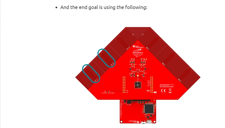
HW:CC2642R1/CC2552R1 Development Kit(2652) Rev:B x 3 ; BOOSTXL-AOA x 1
SDK: SimpleLink CC12x2 26x2 SDK - 3.20.00.68
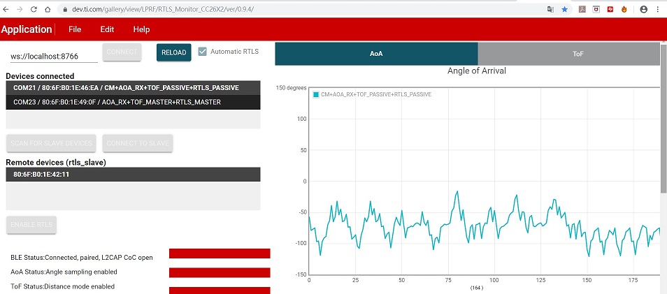
Case 1.
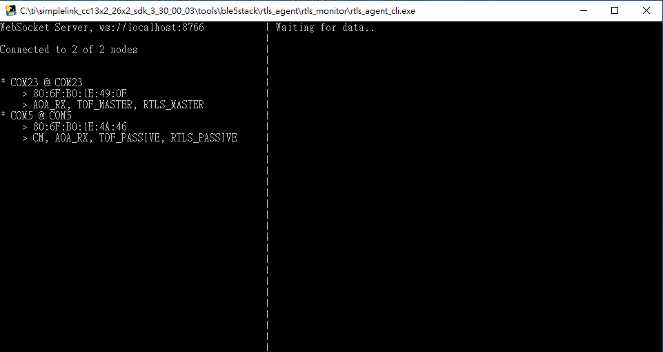
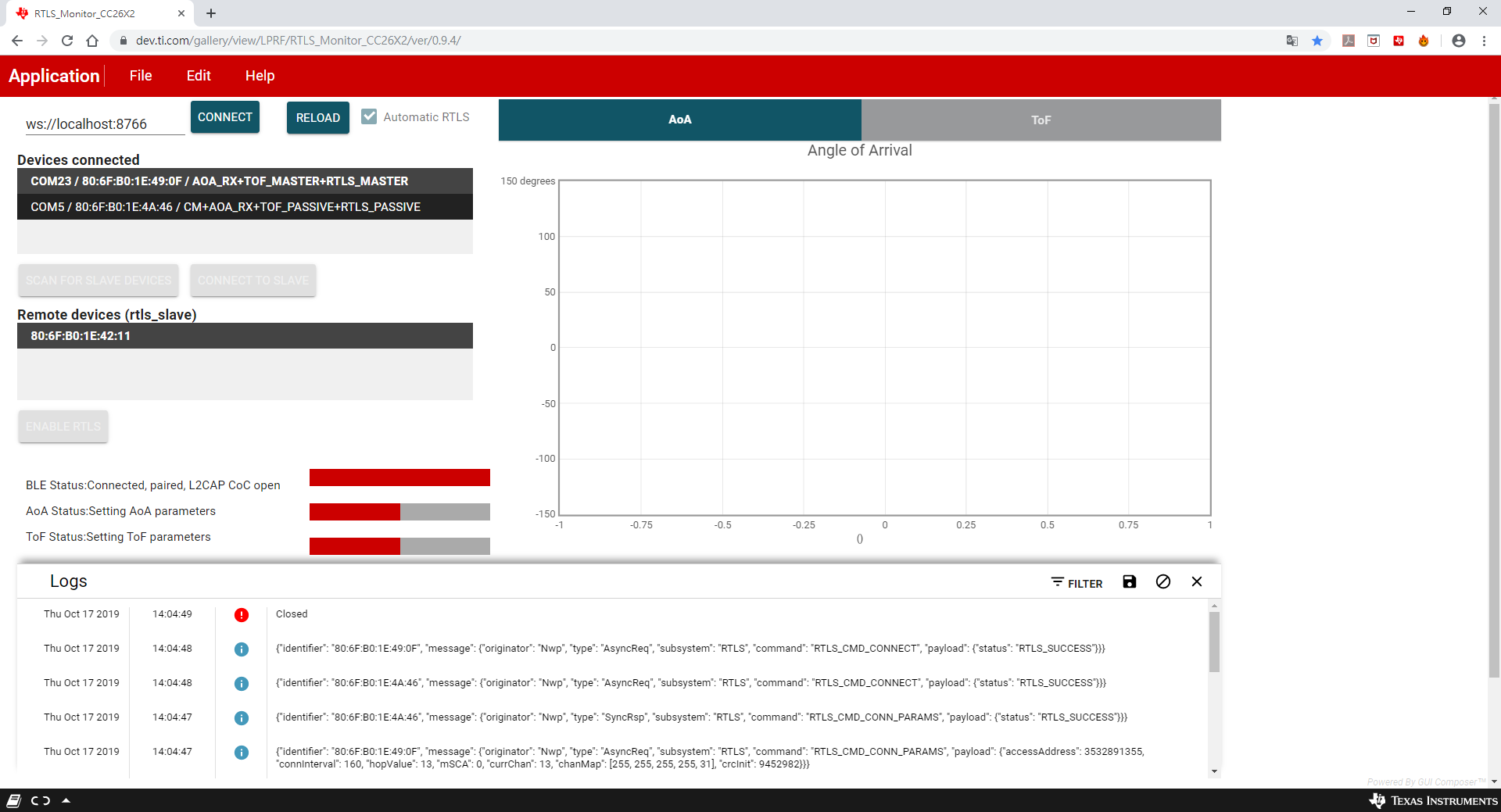
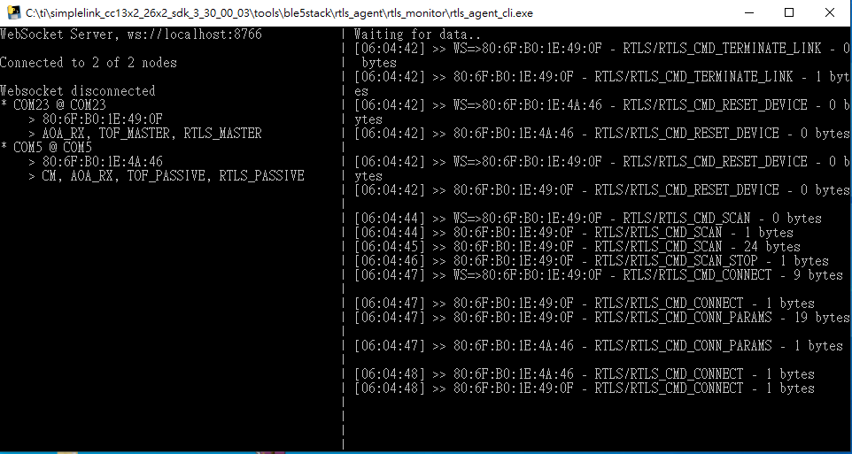
SDK :3.20.00.68 build default code r(tls_master,rtls_slave,rtls_passive)
reference guide: RTLS Toolbox Fundamentals
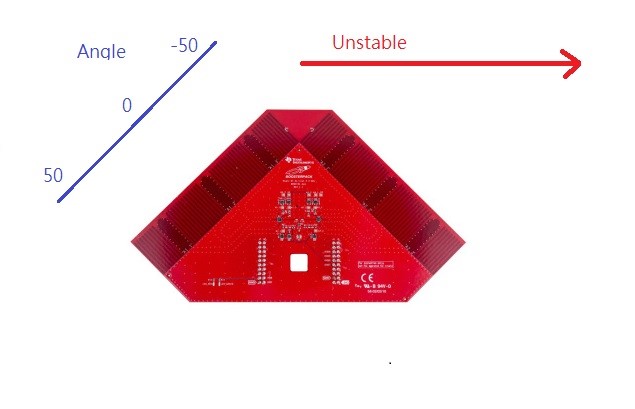
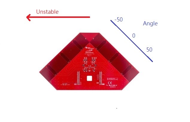
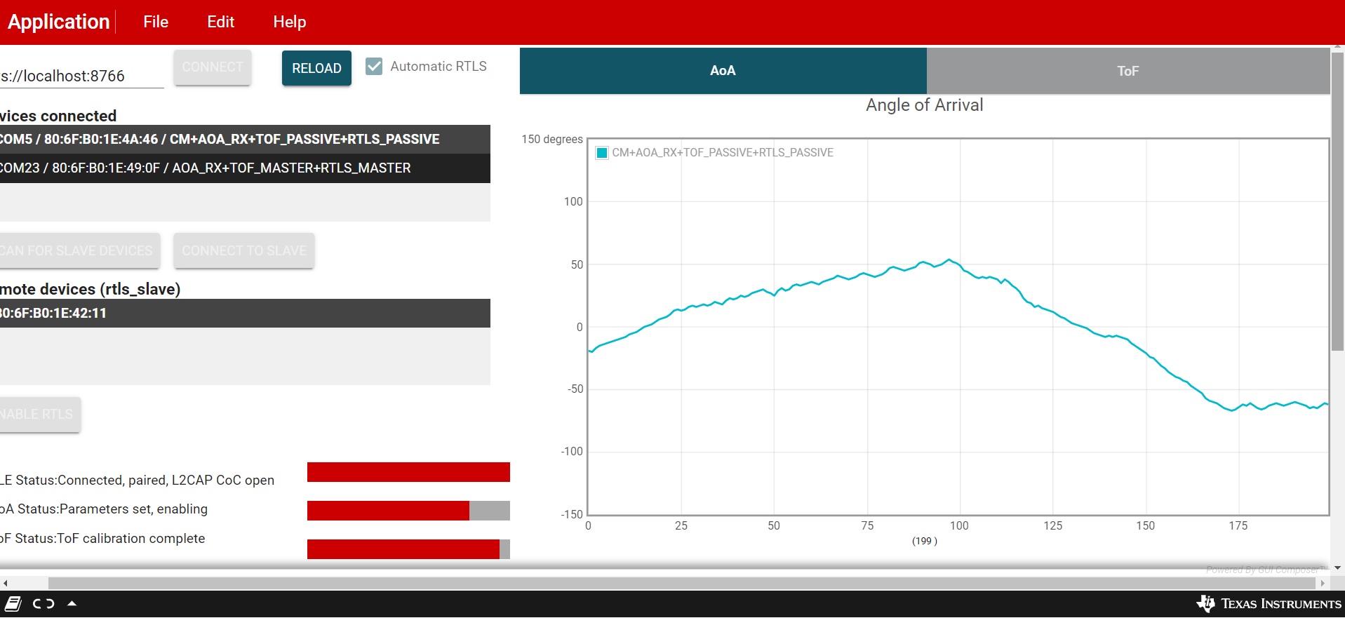
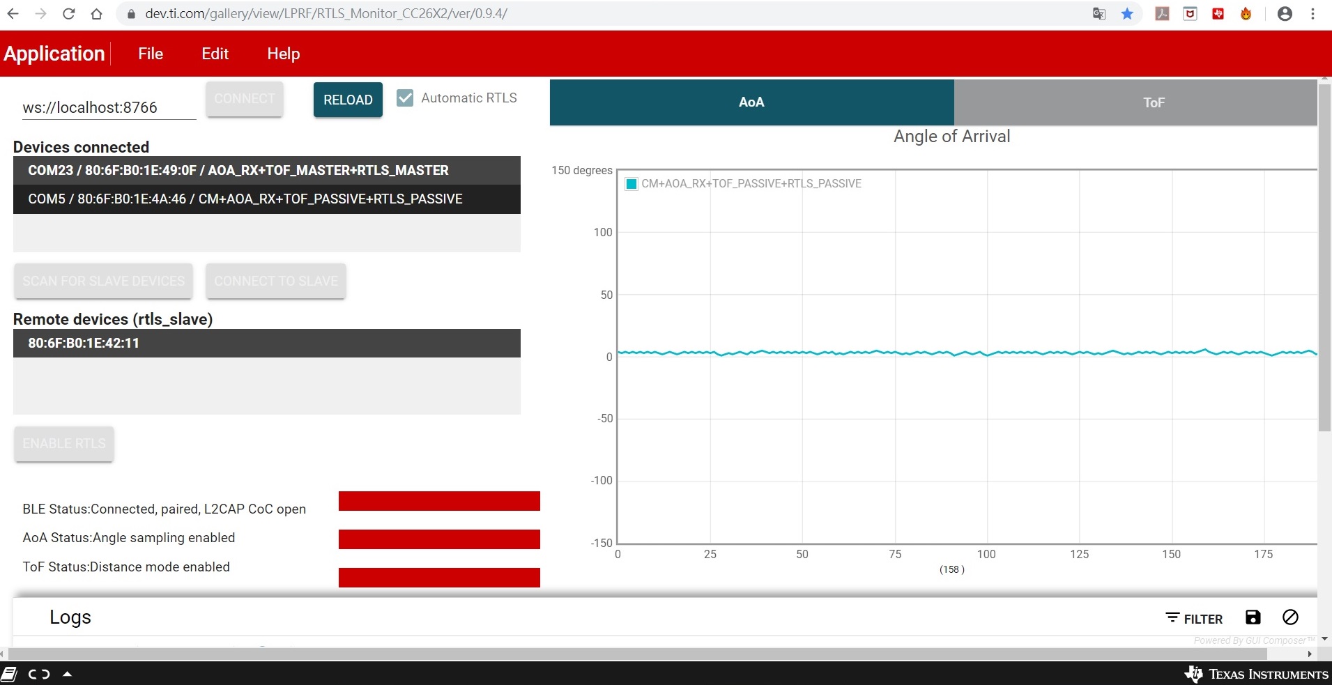
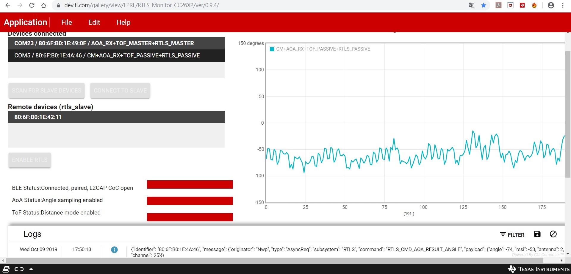
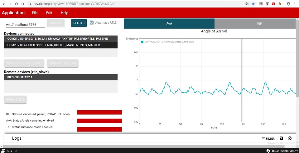
issue: angle is unstable.
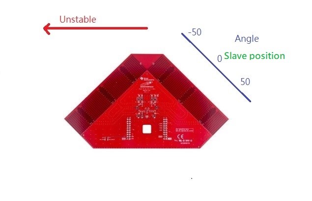
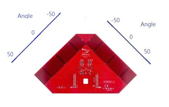
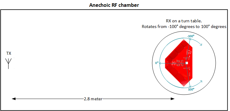
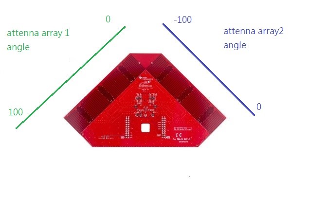
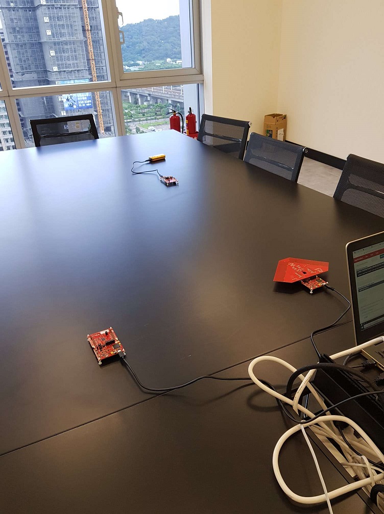
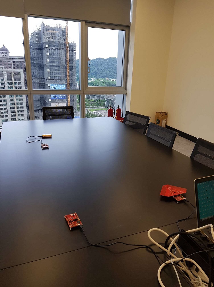
Setup environment

Angle : 0 degree
environment
result
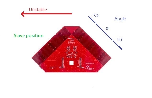
Angle : 30 degree
environment
result
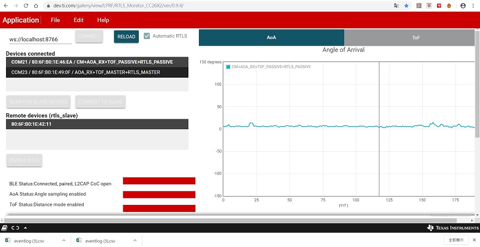
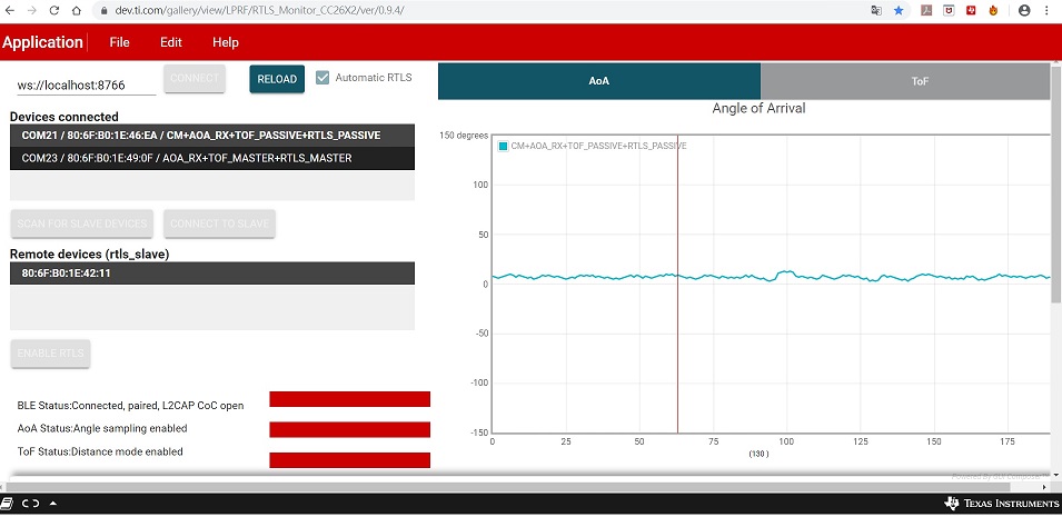
Case 2:
guide:Angle of Arrival(AOA) , according guide modify 3.20.00.68 code change to one antenna,
issue: whatever change slave position, the the measuring angle isn't change almoust(the value about 6 angle)
Angle : 0 degree
result
Angle : 30 degree
result
Best regards,