This thread has been locked.

If you have a related question, please click the "Ask a related question" button in the top right corner. The newly created question will be automatically linked to this question.

CC2640R2F: Locked up after programming

Part Number: CC2640R2F
Other Parts Discussed in Thread: UNIFLASH

Hello,

I have a customer with an issue with their CC2640R2F custom board. The application is a battery application where the battery is epoxied to the hardware so it is not removable. The system lives in one of 3 states: shelf, awake, and active. The idea is that while it is in "shelf" mode it will be ultra low power and be able to wait for the customer to wake it up. The system should be able to live in this state for a long time, year(s). The current measurement numbers using the XDS110 with energy trace indicates that this should be doable, measuring ~1-3ua. With the production intent prototype parts they are seeing a significantly higher current draw that is depleting the battery in under 2 weeks. The simple order of operations for building the boards is:

Flash a program that fully disable the chip

Epoxy the battery to the board and let fully cure

Flash the production code onto the chip 

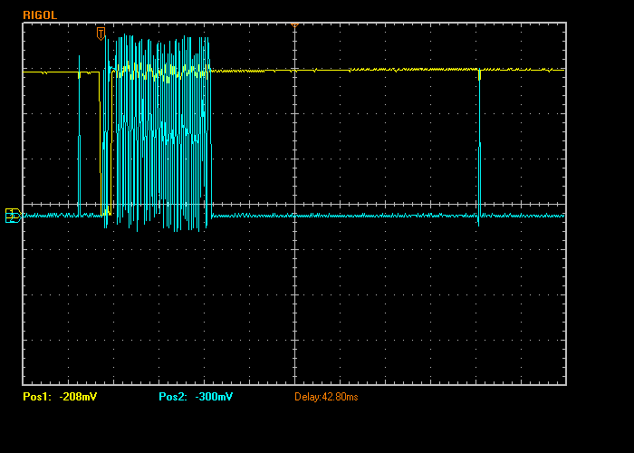
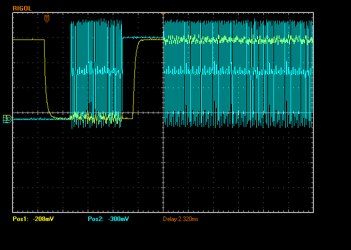
I was able to track the issue down to the way the chip is left after the part is programmed. The micro appears to be stuck in some sort of active state as apposed to executing the production code. If I force a reset by pulling the reset line on the micro the chip seems to start executing the correct code and function as expected. They are using Flash Programmer 2 and it indicates that it is successfully performing a reset on the chip after successfully programming the chip. I have been able to verify this on multiple parts and multiple times on the same parts.

The customer is able to move forward knowing they need to manually reset the chip after programming. I would like to provide them a solution that doesn't require the manual reset and an answer as to what is happening to the chip during programming.

Thanks in advance for the help!

  • Hi,

    I sent it to a concerned engineer. We will get back to you ASAP. Please bear with us.

    Thanks,

    PM

  • Hi Michael,

    A system reset is required after programming to ensure the program counter actual moves to the start of the new program. This is common and should be handled by the flash programmer.

    Regards,
    Fredrik

  • Hi Fredrik,

    I 100% agree. The problem is the flash programmer is NOT properly resetting the chip. It is leaving the chip in an unknown state that has a significant power draw. The way I am able to recover the chip is to manually perform a reset by pulling the reset line low. The flash programmer software states it is successfully resetting the chip but based on the state I observe it is not. I am trying to figure out where the source of this issue is coming from. I am not sure if the programmer is doing something to the chip after it actually performs a reset or if it is failing to perform the reset. Any places you could point me to that I should investigate that may give me an answer would be greatly appreciated.

    Thanks,

    Mike

  • Hi Mike,

    Are you using SmartRF Flash Programmer 2 wire Jtag or UART to program the CC2640R2F. If you use 2 wire JTAG but not connect nRESET, it will program the board but not reset, from my experience, and there is a error message at Smart RF Flash Programmer 2.

    But if you are using UART should be no problem. If there is then try to do same using Launchpad, if there is no problem resetting the CC2640R2F Launchpad after programming, then maybe you have a circuit problem with your custom board.

    -kel

  • Hi Kel,

    We are using 2 wire Jtag with the nReset pin connected. The Flash Programmer 2 indicates in the status window that the chip was successfully reset after programming. The chip does not behave like it has been reset, or at least something was done to it after the reset. 

    Any other thoughts on potential sources for the issue?

    Thanks,

    Mike

  • Hi Mike,

    Would you be able to do a logic capture of the JTAG and reset lines at the end of the programming sequence?

    Regards,
    Fredrik

  • Hi Fredrik,

    Below are a couple screen captures of the programming event. The first second image is a closer look of the first image. First image is 10 ms/div and second image is 500 us/div, both are 1 v/div. Channel 1 (yellow) is the reset line and channel 2 (green) is the TCK. The scope was set to trigger off of the falling edge of the reset line. You can see there is still activity after the last reset. Any idea on what it could be doing after the last reset? Where would I look for what is controlling what the programmer is doing during the programming sequence?

    Thanks,

    Mike

  • Hi Fredrik,

    Any thoughts as to what could be going on? Is there any other information that could be helpful?

    Thanks,

    Mike

  • Hi Mike, 

    It should not be any activity on the TCK-line after the final reset. This can cause the JTAG-domain to wake up. What type of programmer/debugger are you using?

    -Simon

  • Hi Simon,

    I am using an xds110 probe to program the part.

    Let me know if there is anything you would like me to try or verify.

    Thanks,

    Mike

  • Hi Mike, 

    What XDS110 FW version are you on? You can check that with the xdsdfu tool:

    C:\ti\ccs_base\common\uscif\xds110> .\xdsdfu.exe -e

    The latest version is 3.0.0.5. 

    -Simon

  • Hi Simon,

    It looks like I am running 2.3.0.18. I just ran an update with CCS and I am now at 3.0.0.5. I will try programming the chip again with the latest firmware. I'll let you know what I find.

    Thanks,

    Mike

  • Mike, 

    Let me know if I can close this issue. 

    -Simon

  • Hi Simon,

    I finally got a chance to test with the latest xds110 firmware. Sadly I am still seeing the same behavior. I had to use CCS to program instead of Flash Programmer 2 because Flash Programmer 2 was reverting the firmware back to 2.3.0.18. I was able to get CCS to program and I verified the xds110 firmware was at the latest, 3.0.0.5.

    Any other thoughts on what could be going on? Anything else I can look into to help?

    Thanks,

    Mike

  • Mike, 

    Do you see the same behaviour in with both Flash Programmer and CCS? What happens if you use Uniflash?

    -Simon

  • Simon,

    I see the same result with both CCS and Flash Programmer. I see the continued clock cycles on the TCK pin after the last reset pulse occurs. I downloaded and attempted Uniflash. I can not get it to connect to the board but I can get Flash Programmer 2 to connect and program. Uniflash just gives me this error:

    I attempted to run the re-sync to see if it would help and now whenever I do anything that tries to connect to the device I get this error:

    I'm not sure what is going on with Uniflash but it has created a completely different set of problems and doesn't resolve the initial issue.

    Any other thoughts?

    Thanks,

    Mike

  • Hi Mike

    What version of Flash Programmer 2 are you using? Are you using the GUI or the CLI version?

    Regards,
    Vegard

  • Hi Simon,

    I am using version 1.8.1 which I believe is the newest version. I am using the GUI. Does  the CLI operate any differently?

    Thanks,

    Mike

  • Hi Mike.

    The CLI does not operate differently, but you can issue a reset through the CLI as a workaround. 

    Regards,
    Vegard

  • Hi Mike.

    There will be a new version of Flash Programmer 2 that will hopefully fix this problem. Were you able to resolve this on your end?

    Regards, 
    Vegard

  • Hi Vegard,

    I haven't tried implementing the programming using the CLI. The customer has been manually resetting the chip after programming and that has been working well enough for now. Do you know an approximate release date for the new version of Flash Programmer 2? Is this a known problem they are addressing with the updated version of the Flash Programmer? 

    Thanks,

    Mike