This thread has been locked.

If you have a related question, please click the "Ask a related question" button in the top right corner. The newly created question will be automatically linked to this question.

CCS/CC2642R: SYN_PROG_ERR for CC2642

Part Number: CC2642R
Other Parts Discussed in Thread: CC2640

Tool/software: Code Composer Studio

Hi Ti Experts,

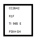
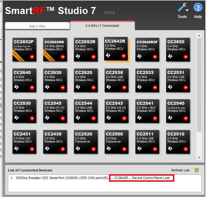
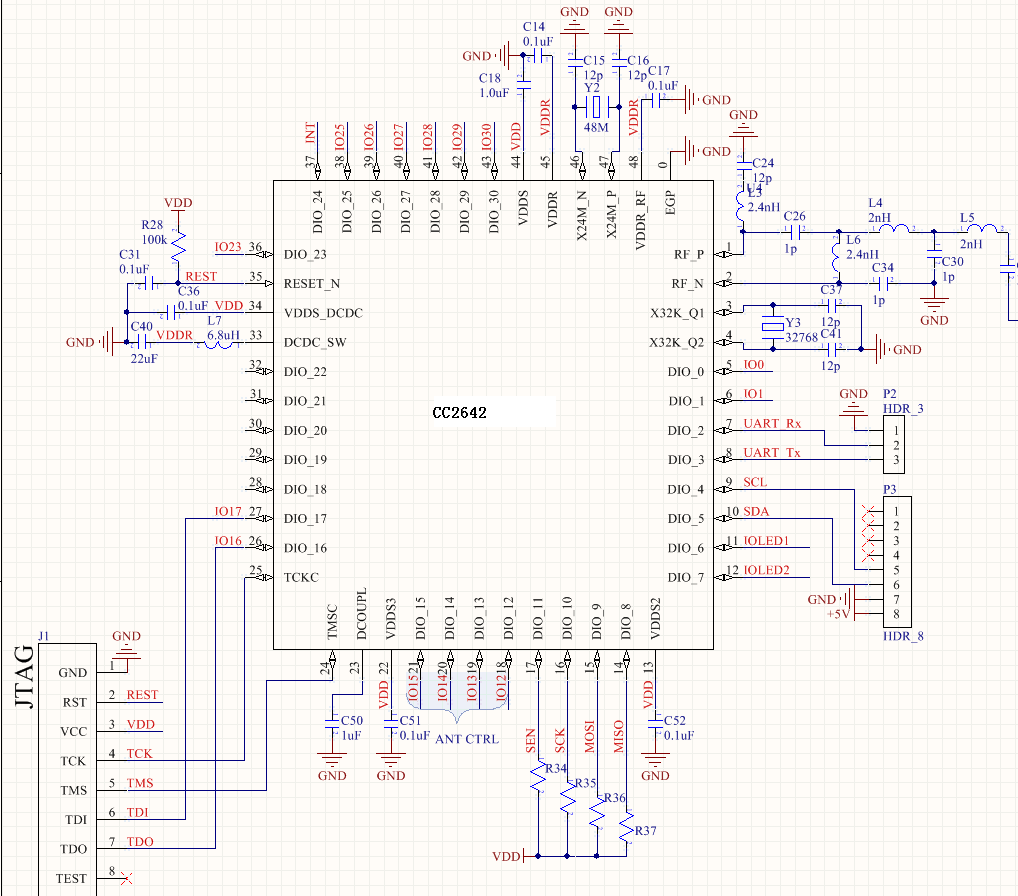
We are trying to switch from CC2640 to 2642... we designed our own board (as below) and debug project with CCS + XDS200 probe. 


2 things we have met:

1,  with respect to AOA passive project demo (from SDK), UART baud rate is measured only 38400, which is 1/3 of 115200 as desired. Other project demo (from SDK) doesn't seem to have this issue.

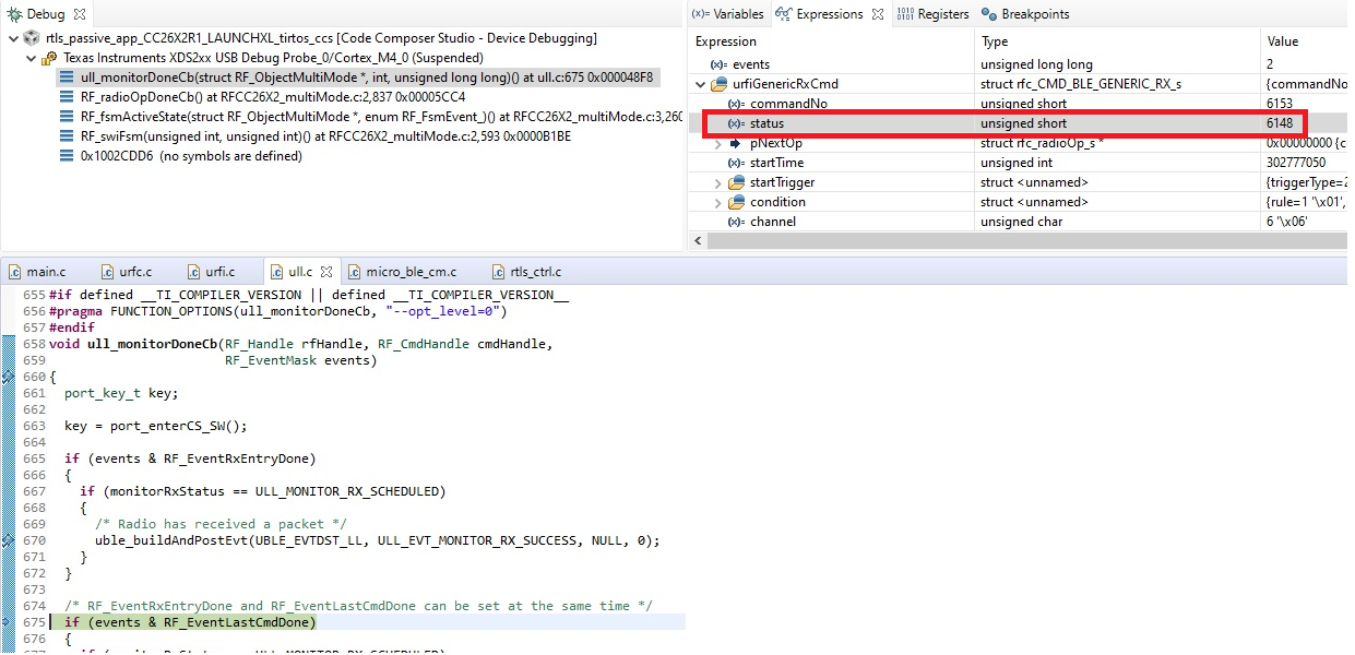
2, project was not able to receive AOA data. CCS break-point debug indicates RF status error of SYN_PROG_ERR (as below).


I checked VDDR, it is around 1.67V range. The 48M crystal is 2-pin passive component (No GND Pin), do i have to use 4-pin package instead?

Please let me know if there is anything i can try to solve this. 

Thanks in advance,

TL


  • - In SmartRF Studio, is the chip you are using recognized as a CC2642, rev E? 

    - Have you tried to run the empty, uartecho and  rfCarrierWave example from the SDK to see if any of these are running as intended? With a small example it could be easier to see why your program isn't running. Also see the "board bring-up" section in http://www.ti.com/lit/an/swra640c/swra640c.pdf if you have not already stepped through it. 

    I have to double check the expected UART speed in the RTLS example. 

  • Hi TER,

    Thanks for your kind advice.

    I think my device is rev E from the marks "CC2642R1F TI 965 E", but Smart RF Studio recognizes as "CC2642" and reports error of 0x0809.

    (it is hard to take a clear picture on device marking)

    I looked into swra640c doc especially "board bring-up" chapter, but still do not have a good clue to my case. I suspect that the 48M crystal may not working properly and then results this error code as well as incorrect UART baud rate. Since measuring crystal pin with analyzer is not preferred, is there any approach to measure the oscillating frequency? One more point, is the UART clock sourced/divided from 48M OSC? if yes, this might be able to explain both things at the same time.

    Appreciate if any further ideas.

    Thanks!

  • Did you test empty, uartecho and  rfCarrierWave as suggested? If the 48 MHz fails, you will be able to run the first 2 examples but not the last.

    What is the spec of your xtal? (in addition a link to a datasheet would be nice)

  • Hi TER,

    Just tried 3 projects... yes both empty & uart echo works fine while rfCarrier (step debug info) reports status error of 0x0809 then 0x0808.

    Below is the 48M spec on my board. If the 48M is not good enough, i will try to replace it to another vendor.


  • What is the ESR of this xtal? If you look on the 48 MHz part of the "clock specifications part" of the datasheet it's listed the required spec of the xtal. 

  • hi TER,

    thanks again for your kind support and quick response.

    Just confirmed the 48M is the criminal. I measured it by spectrum analyzer, found it actually oscillates at 16Mhz (though marks 48M part number on top).

    T.L.