This thread has been locked.

If you have a related question, please click the "Ask a related question" button in the top right corner. The newly created question will be automatically linked to this question.

CC2640R2F: design PCB board and Schematic

Part Number: CC2640R2F
Other Parts Discussed in Thread: LAUNCHXL-CC2640R2, CC2650, SYSCONFIG

Hi TI support team,

I am starting to design PCB board

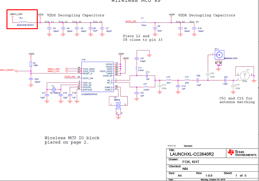
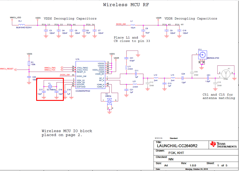
I have reference from LAUNCHXL-CC2640R

I need to use the nessary component for bluetooth communication such as CC2640R2F chip, Crystal, Antenna and component that related.

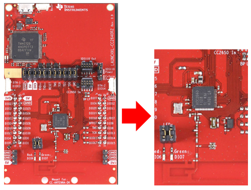
1. Can I use CC2640R2 bluetooth by keeping only nessary component for reducing PCB size as figure below ?

2. What the component can I cut and keep ?

3. please tell us about PCB size that I can use ?

Please advise 

Note: LAUNCHXL-CC2640R2_1_0_0_Schematics

4426.LAUNCHXL-CC2640R2_1_0_0_Schematics.pdf

Thank you

Best Regards,

  • Hi, 

    I add question as below

    How much PCB thickness for TI design 1.6 mm ?


    Thank you

    Best Regards,


  • Hi. 

    If you are designing a custom board I recommend you read through CC13xx/CC26xx Hardware Configuration and PCB Design Considerations. In this report, on page 6, you can find reference designs for the different devices. The CC2640EM-CXS is a small design with only the required BLE components that you can base your design on that uses the CC2640R2F device. 

    In chapter four of the same document, you can find the recommended board stack-up, which is 1.6 mm.

    Regards, 
    Vegard

  • Hi,

    Note with thanks

    From the CC2640EM-CXS schematic, it use CC2640R2FYFV

    If I use CC2640R2FRGZR, Can I replace chip and follow this schematic ?


    Thank you

    Best Regards,

  • Hi

    Since the CC2650 and CC2640R2F is pin compatible, I recommend instead following the CC2650EM-7ID schematic and replacing the chip with a CC2640R2F. 

    Regards, 
    Vegard

  • Hi Vegard,

    Many thanks for your response

    For schematic in LAUNCHXL-CC2640R2 is difference CC2640EM-CXS at RF_P and RF_N

    1. How is the performance difference ?

    2. Which one the schematic should I follow ?


    Thank you

    Best Regards,


  • Hi

    The schematic for the LAUNCHXL-CC2640R2F uses differential internal biased RF output, while the schematic for the CC2640EM uses single ended external biased RF output. These different outputs have different performance and BOM cost. If you want the best performance but the highest BOM cost, go with a differential externally biased output. You can read more about the different front-end configurations in chapter 2 in the Hardware Configuration and PCB Design Considerations application report.

    Regards, 
    Vegard

  • Hi Vegard,

    Many thanks for information

    Do you have schematic and gerber file for the small design with only the required BLE components and using differential internal biased RF output ?

    Could I get that file and can you convert to Altium in version 19.0.12, please ?

    Thank you

    Best Regards,

  • The CC2650EM-7ID uses differential output internal bias. The design files for this can be found here http://www.ti.com/lit/zip/swrc298. Unfortunately I do not have these in Altium files. 

    Regards,
    Vegard

  • Hi Vegard,

    Note with thanks 

    I have questions

    1. What is PCB size for the CC2650EM-7ID ?

    2. About VDDR and DCDC_SW use for ?, Can I no connect the VDDR, VDDR_RF and DCDC_SW pins ? and How I should do if no connect (leave open/connect to GND) ?

    3. Is the FL1 necessary to connect ?, Can I remove this component ?

    4. If I not use external 32.768kHz, How I should do if no connect (leave open/connect to GND) ?

    please explan and advise


    Thank you

    Best Regards,


  • Hi

    1. The dimension of the board can be found in the Mech_Drawing.pdf file in the zip folder, for this device the dimensions are 40.9x46.9 mm.
    2. If you look  in chapter 9 in the CC13xx/CC26xx Hardware Configuration and PCB Design Considerations application report, you can see the different power supply configurations. You need to follow one of these.
    3. I am unsure, I will get back to you on this question
    4. You can leave these pins floating. 

    Regards,
    Vegard

  • For your question No. 2: you need those for proper CC2640R2F operation.

    For your question No. 3: you can leave it open, but you need to use internal oscillator, which is enabled at code.

    -kel

  • Hi Vegard,

    Note with thanks

    I will use differential output internal bias by reference schematic from LAUNCHXL-CC2640R2_1_0_0_Schematics only page 1

    1. I need to use BLE, Can I no connect X32K_Q1 and X32K_Q2 ?

    2. What the other component can I remove in this schematic ?

    Thank you

    Best Regards,


  • Hi Vegard,

    I add my question 

    From  LAUNCHXL-CC2640R2_1_0_0_Schematics page 2

    3. It is connected with External flash, Is it use for supporting over the air download, right ?

    https://e2e.ti.com/support/wireless-connectivity/bluetooth/f/538/t/855458

    4. If I want to use this feature, What pin of CC2640R2FRGZ need to connect ?

    Thank you

    Best Regards,


  • Hi

    1. It is possible to remove the XOSC and still use BLE, there is a application report on this topic here: http://www.ti.com/lit/an/swra499c/swra499c.pdf 
    2. If you switch to Global LDO mode, you can remove some of the DCDC components, read chapter 9.3 here: https://www.ti.com/cn/lit/an/swra640c/swra640c.pdf
    3. The external flash can be used for OAD, but it depends on the application what you use it for. 
    4. The UART and SPI pins can be mapped to every available GPIO on on the chip, you can decide which pins to use in SysConfig

    Regards, 
    Vegard.

  • Hi Vegard,

    For your answer no.4, The UART and SPI I can configure

    From https://www.ti.com/cn/lit/an/swra640c/swra640c.pdf about Bootloader pins on page 12

    The UART and SPI are fixed pin and cannot be reconfigured, right ?

    So example if I use UART, Should I use DIO2 and DIO3 right ?

    Thank you

    Best Regards,

  • Hi

    Correct, if you want to use the UART for bootloader, you need to use pin 2 and 3. 

    Regards, 
    Vegard

  • Hi,

    I have changed the UART bootloader pins to pin 7 and 8 before. You can set this at board files.

    -kel

  • Markel, 

    How did you change these pins in the board file? The UART Bootloader pins are hardcoded into the ROM image, you need to use DIO2 and DIO3 for the bootloader.

    Regards, 
    Vegard

  • Hi Vegard,

    Pin 2 and Pin 3 will not always be available when you do custom PCB. I simply changed it at CC2640R2F_LAUNCHXL.h. Works in production programming using UART.

    #define CC2640R2_LAUNCHXL_UART_RX               IOID_2          /* RXD */
    #define CC2640R2_LAUNCHXL_UART_TX               IOID_3          /* TXD */

    CC2640R2F_LAUNCHXL.c

    /*
     *  =============================== UART ===============================
     */
    #include <ti/drivers/UART.h>
    #include <ti/drivers/uart/UARTCC26XX.h>
    
    UARTCC26XX_Object uartCC26XXObjects[CC2640R2_LAUNCHXL_UARTCOUNT];
    
    uint8_t uartCC26XXRingBuffer[CC2640R2_LAUNCHXL_UARTCOUNT][32];
    
    const UARTCC26XX_HWAttrsV2 uartCC26XXHWAttrs[CC2640R2_LAUNCHXL_UARTCOUNT] = {
        {
            .baseAddr       = UART0_BASE,
            .powerMngrId    = PowerCC26XX_PERIPH_UART0,
            .intNum         = INT_UART0_COMB,
            .intPriority    = ~0,
            .swiPriority    = 0,
            .txPin          = CC2640R2_LAUNCHXL_UART_TX,
            .rxPin          = CC2640R2_LAUNCHXL_UART_RX,
            .ctsPin         = PIN_UNASSIGNED,
            .rtsPin         = PIN_UNASSIGNED,
            .ringBufPtr     = uartCC26XXRingBuffer[CC2640R2_LAUNCHXL_UART0],
            .ringBufSize    = sizeof(uartCC26XXRingBuffer[CC2640R2_LAUNCHXL_UART0]),
            .txIntFifoThr   = UARTCC26XX_FIFO_THRESHOLD_1_8,
            .rxIntFifoThr   = UARTCC26XX_FIFO_THRESHOLD_4_8,
            .errorFxn       = NULL
        }
    };
    
    const UART_Config UART_config[CC2640R2_LAUNCHXL_UARTCOUNT] = {
        {
            .fxnTablePtr = &UARTCC26XX_fxnTable,
            .object      = &uartCC26XXObjects[CC2640R2_LAUNCHXL_UART0],
            .hwAttrs     = &uartCC26XXHWAttrs[CC2640R2_LAUNCHXL_UART0]
        },
    };
    
    const uint_least8_t UART_count = CC2640R2_LAUNCHXL_UARTCOUNT;

    -kel

  • If you are using the TI Bootloader, see table 8-2 in the TRM for information on which DIOs you must use. 

    -Simon