This thread has been locked.

If you have a related question, please click the "Ask a related question" button in the top right corner. The newly created question will be automatically linked to this question.

CCS/CC2640R2F: Trouble outputting HW Timer on a pin

Part Number: CC2640R2F

Tool/software: Code Composer Studio

Hello all,

I'm attempting to create a hardware timer and output said timer on a pin by modifying the registers. I'm following the steps detailed in the technical reference manual as shown:

______________________________________________________________________________________________________________________________

1. To use a GPT module, enable the peripheral domain and the appropriate GPT module in the PRCM by
         * writing to the PRCM:GPTCLKGR, the PRCM:GPTCLKGS, and the PRCM:GPTCLKGDS registers, or
         * by using the following driver library functions:
         * PRCMPeripheralRunEnable(uint32_t, ui32Peripheral)
         * PRCMPeripheralSleepEnable(uint32_t, ui32Peripheral)
         * PRCMPeripheralDeepSLeepEnable(uint32_t, ui32Peripheral)
2. Next, load the setting to the clock controller by writing to the PRCM:CLKLOADCTL register
3. Configure the IOC module to route the output from the GPT module to the IOs.

and also:

The GPTM is configured for one-shot and periodic modes by the following sequence:
1. Ensure the timer is disabled (clear the GPT:CTL TnEN register bit) before making any changes.
2. Write the GPTM Configuration Register (GPT:CFG) with a value of 0x00000000.
3. Configure the GPTM Timer n Mode Register (GPT:TnMR) TnMR field:
(a) Write a value of 0x1 for one-shot mode.
(b) Write a value of 0x2 for periodic mode.
4. Optionally, configure the GPT:TnMR TnSNAPS, TnWOT, TnMTE,and TnCDIR register bits to select whether to capture the value of the free-running timer at time-out,use an external trigger to start counting,configure an additional trigger or interrupt,and count up or down.
5. Load the start value into the GPTM Timer n Interval Load Register (GPT:TnILR).
6. If interrupts are required,set the appropriate bits in the GPTM Interrupt Mask Register (GPT:IMR).
7. Set the GPT:CTLTnEN register bit to enable the timer and start counting.
8. Poll the GPT:MRIS register or wait for the interrupt to be generated(if enabled). In both cases,the status flags are cleared by writing a 1 to the appropriate bit of the GPTM Interrupt Clear Register (GPT:ICR)

_____________________________________________________________________________________________________________________________

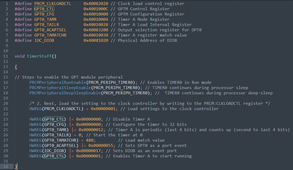
A bit of pseudo-code for what I have:

#define PRCM_CLKLOADCTL     0x40082028 // Clock load control register
#define GPT0_CTL            0x4001000C // GPTM Control Register
#define GPT0_CFG            0x40010000 // GPTM Configuration Register
#define GPT0_TAMR           0x40010004 // Timer A Mode Register
#define GPT0_TAILR          0x40010028 // Timer A Load Interval Register
#define GPT0_ACAPTSEL       0x40083200 // Output selection register for GPT0
#define GPT0_TAMATCHR       0x40010030 // Timer A register match value
#define IOC_DIO8            0x40081020 // Physical Address of DIO8


void timerStuff()

{

// Steps to enable the GPT module peripheral
      PRCMPeripheralRunEnable(PRCM_PERIPH_TIMER0); // Enables TIMER0 in Run mode
      PRCMPeripheralSleepEnable(PRCM_PERIPH_TIMER0); // TIMER0 continues during processor sleep
      PRCMPeripheralDeepSleepEnable(PRCM_PERIPH_TIMER0); //  TIMER0 continues during processor deep-sleep

      /* 2. Next, load the setting to the clock controller by writing to the PRCM:CLKLOADCTL register */
      HWREG(PRCM_CLKLOADCTL) = 0x00000001; // Load settings to the clock controller

      HWREG(GPT0_CTL) |= 0x00000000; // Disable Timer A
      HWREG(GPT0_CFG) |= 0x00000000; // Configure the timer to 32 bits
      HWREG(GPT0_TAMR) |= 0x00000012; // Timer A is periodic (last 4 bits) and counts up (second to last 4 bits)
      HWREG(GPT0_TAILR) = 0; // Start the timer at 0
      HWREG(GPT0_TAMATCHR) = 480;         // Load match value
      HWREG(GPT0_ACAPTSEL) |= 0x00000055; // Sets GPT0 as a port event
      HWREG(IOC_DIO8) |= 0x00000017; // Sets DIO8 as an event port
      HWREG(GPT0_CTL) |= 0x00000001; // Enables Timer A to start running

}

My code will compile, but I am unable to see the timer output on the desired pin. I'm unsure if my issue is with the order I am writing to the registers, or if I'm setting the output on the pin wrong. Any assistance would be greatly appreciated.

Thanks for your time.

Best,
Nick

  • I expected the file to just display on the site, but it isn't on my end, so I'm attaching an image of the file:

  • We only give very limited support for bare metal related questions. Please look into using the drivers directly (APIs http://dev.ti.com/tirex/explore/node?a=VLyFKFf__3.6.2&node=ADfS7ixpgUmHy56H6NON4Q__krol.2c__LATEST&r=VLyFKFf__LATEST) or look into the driver code on how the drivers uses the driiverlib functions.

  • So my original attempt to create the timer was with the drivers. After looking into them again and trying to follow the steps listed in the TRM, I am still unable to get a timer output to the pin.

    For some reason, the syntax highlighter is not working, but my code so far is below:

    ________________________________________________________________________________________________________________________

    #include <unistd.h>
    #include <stdint.h>
    #include <stddef.h>

    /* Driver Header files */
    #include <ti/drivers/GPIO.h>
    #include <ti/drivers/pin/PINCC26XX.h>
    #include <ti/drivers/Power.h> // prevent power down during standby mode
    #include <ti/drivers/power/PowerCC26XX.h>
    #include <ti/devices/cc26x0r2/driverlib/timer.h> // new code: include for timer disabling, enabling, and configuration
    #include <ti/devices/cc26x0r2/driverlib/ioc.h> // new code: include driver library for ioc api's
    #include "ti/drivers/timer/GPTimerCC26XX.h" // new code: GPtimter header file include
    #include <ti/devices/cc26x0r2/driverlib/prcm.h> // new code: includes the drivers for the prcm library
    #include <ti/drivers/pin/PINCC26XX.h> // new code: header for pin functions
    // #include <ti/drivers/I2C.h>
    // #include <ti/drivers/SDSPI.h>
    // #include <ti/drivers/SPI.h>
    // #include <ti/drivers/UART.h>
    // #include <ti/drivers/Watchdog.h>

    /* Board Header file */
    #include "Board.h"

    static PIN_Handle hPin;
    static PIN_State hPinState;
    static PIN_Config hPinTable[] =
    {
      PIN_ID(8)   | PIN_GPIO_OUTPUT_EN | PIN_GPIO_LOW | PIN_PUSHPULL | PIN_DRVSTR_MAX,
      PIN_TERMINATE
    };

    /*
     *  ======== mainThread ========
     */
    void *mainThread(void *arg0)
    {
        hPin = PIN_open(&hPinState, hPinTable);
        /* Set constraints for standby and idle power down */
        Power_setConstraint(PowerCC26XX_IDLE_PD_DISALLOW); // new code: disables idle power down
        Power_setConstraint(PowerCC26XX_SB_DISALLOW); // new code: disables standby power down

        // Steps to enable the GPT module peripheral
        PRCMPeripheralRunEnable(PRCM_PERIPH_TIMER0); // Enables TIMER0 in Run mode
        PRCMPeripheralSleepEnable(PRCM_PERIPH_TIMER0); // TIMER0 continues during processor sleep
        PRCMPeripheralDeepSleepEnable(PRCM_PERIPH_TIMER0); //  TIMER0 continues during processor deep-sleep
        PRCMLoadSet(); // Loads settings to the clock controller

        TimerDisable(GPT0_BASE, TIMER_BOTH); // disables both Timer A and Timer B for GPT0
        TimerConfigure(GPT0_BASE, TIMER_CFG_PERIODIC); // Sets GPT0 as a periodic, count up timer
        TimerLoadSet(GPT0_BASE, TIMER_A, 480); // Loads a value of 480 cycles into the timer
        IOCPortConfigureSet(IOID_8, IOC_PORT_MCU_PORT_EVENT0, IOC_IOMODE_NORMAL); // set DIO8 to output the gpt0 timer event
        PINCC26XX_setMux(hPin, PIN_ID(8), IOC_IOCFG8_PORT_ID_PORT_EVENT0); // sets DIO8 to the pin for event0
        TimerEnable(GPT0_BASE, TIMER_BOTH); // enables both timers for GPT0


        //IOC_IOCFG8_PORT_ID_PORT_EVENT0


        return 0;
    }

    ________________________________________________________________________________________________________________________

    I don't know if I am doing any of the steps out of order, or if I'm setting the timer to the pin correctly; I've seen no examples to reference.

  • Have you looked into the PWM driver since this uses both PIN/ GPIO and timer? 

  • I haven't looked into using the PWM driver yet. Essentially, my goal is to simply run a timer on a pin in a way that doesn't create any software interrupts.

    Is this possible using the PWM driver?

    A short update from my previous post: I can start up a timer using the GPTimer driver, and can create software interrupts. I've attempted outputting the timer to a pin with the PINCC26XX_setMux function, but no timer ever pulses on the desired pin.

  • It sounded like you had issues with getting a signal from the GPTimer out on a pin. This is done in the PWM driver so if you are not able to use this driver directly you should be able to use the PWM driver code as a guide to do what you want.

  • I was originally under the impression that I could output a signal created by a periodic timer on a pin, but I was mistaken. I've modified the PWM driver code that you mentioned and now  code works perfectly.

    Thank you for the help. I really appreciate it!