This thread has been locked.

If you have a related question, please click the "Ask a related question" button in the top right corner. The newly created question will be automatically linked to this question.

CCS/BOOSTXL-AOA: CCS/LAUNCHXL-CC26X2R1: CC13X2-26X2-SDK_3.40.00.02 – AOA parameters and IQ sampling problem

Part Number: BOOSTXL-AOA

Tool/software: Code Composer Studio

Hello,

I've been trying out the SDK for the CC26X2 (version 3.40.00.02) with a pair of CC26x2R1 as RTLS Master and RTLS Slave (no Passive)

and I'm currently using the rtls_example_with_rtls_util.py and rtls_aoa_iq_with_rtls_util_export_into_csv.py application.


For RTLS Master and RTLS Slave (no Passive), with AOA parameters [sample_rate = 4MHz, slot_duration = 2us] in rtls_aoa_iq_with_rtls_util_export_into_csv.py

It looks normal in first 32 samples as no ANT switching in reference period. 

pic 1: RAW without filtering

pic2: default filtering ANT switch slot

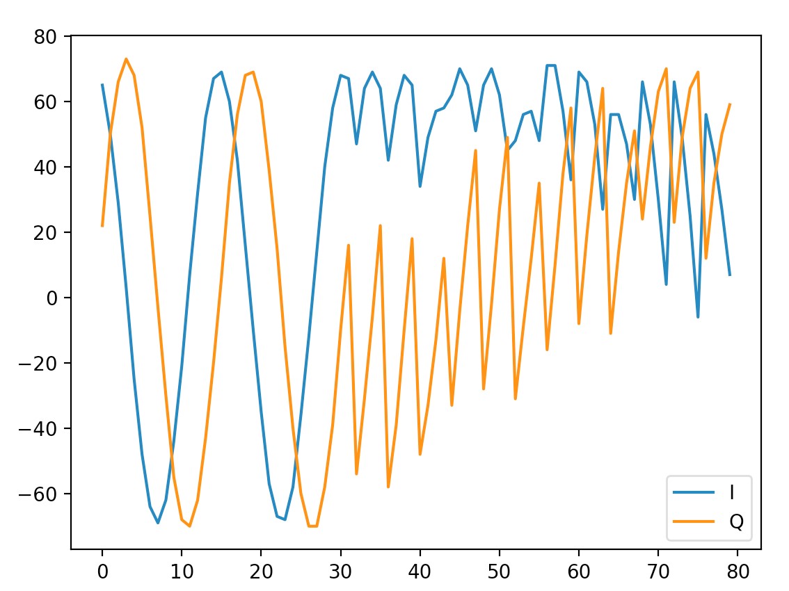
1. in PIC1, why the IQ samples would be across axis every 2 samples?

2. And in PIC2 of IQ plots with default filtering(no antenna switching slot), it didn’t look like a wave during the sampling slot (every 2us, 8 samples),

Does the 2us slot duration means antenna switch + sample slot? Or 2us for each slot?

3. In SDK Hci_event.c LL_SetCteSamples():

I noticed that with default filtering config, the first sample index would be 36 for 1us slot (32 samples in 8us reference period, and 4samples during antenna switch),

but 44 for 2us slot instead of 40 (32 samples in 8us reference period, and 8samples during antenna switch)

Did I miss any information here?

4. In discuss thread https://e2e.ti.com/support/wireless-connectivity/bluetooth/f/538/p/860365/3185273:

Assuming the antenna pattern is [0, 1, 2], does it mean that at the beginning of every session, RSSI will be measured by Antenna 0 during reference period, and after the first antenna switch slot, IQ would be sampled by antenna 1?

Thanks in advance 

Kenny02_14_2020_15_09_53_rtls_raw_iq_samples_filter.csv02_14_2020_15_12_42_rtls_raw_iq_samples.csv

  • Hi Kenny, 

    Assigning an expert to look into your questions.

    Thanks, 
    Elin

  • Hi,

    Q1) First of all, can you confirm you have consulted the AOA welcome page and followed the chapter "Preparations"?

    Q2 and Q3) (And for all the questions regarding CTE timing): Please have a look to the BLUETOOTH CORE SPECIFICATION Version 5.1 | Vol 6, Part B | 2.5.1 and BLUETOOTH CORE SPECIFICATION Version 5.1 | Vol 6, Part B | 2.5.4.
    - The 2us slot duration means antenna switch + sample slot. In other words, you have one antenna switching every 2us.
      [EDIT] The sampling slots (lasting 1us or 2us) are alternate with switching slots (lasting 1us or 2us too). Details can be founded in the “Bluetooth Direction Finding - A Technical Overview” document (especially in the Figure 20 - CTE timing rules).
    -The values used by LL_SetCteSamples() seem correct to me:

    • If you are using 1us then you have 1us switch slot which is dropped and 1us sample slot which are samples you are saving -> as you said, 32 samples + 4 samples from the switching slot = sampling starts at offset 36
    • However, if you are using 2us then you have a 2us switch slot, 1us ‘idle’ slot which allows your antennas to settle and finally 1us sample slot -> 32 samples + 8 samples from the switch slot + 4 samples from the idle slot = sampling starts at offset 44.

    Q4) The thread you mention has not been written for the same SDK.
    For SDK 3.40, the main antenna is set as the first antenna of the patern. The second antenna of the pattern is then used to samples the firs IQ samples after the first antenna switching.
    Please find details in the following code (called in RTLSMaster_setAoaParamsReq() function):

      // Initialize GPIO's specified in ble_user_config.c (antennaTbl)
      // Initialize one of the antenna ID's as the main antenna (in this case the first antenna in the pattern)
      // BOOSTXL-AOA array switch IO is handled by rtls_ctrl_aoa.c
      status = RTLSSrv_initAntArray(pConfig->pAntPattern[0]);

    I hope this will help,

    Kind regards,

  • Hi Clément,

    Q1). Yes, preparations chapter confirmed before the test

    Q2) Q3). So for both 1us and 2us slot duration with 4MHz sampling rate, the "valid" samples within a sampling slot are all 4 samples?

    I referenced how RTLS passive extract IQ samples for pair angle calculation 

    (Passive copy samples from RF RAM, and only support 4MHz 2us)

    It seems the valid samples within a sampling slot is 8

    #define AOA_NUM_VALID_SAMPLES 8
    #define AOA_OFFSET_FIRST_VALID_SAMPLE 8
    #define AOA_NUM_SAMPLES_PER_BLOCK 16

    AOA_getPairAngles()

    for (uint16_t i = AOA_OFFSET_FIRST_VALID_SAMPLE; i < AOA_NUM_VALID_SAMPLES + AOA_OFFSET_FIRST_VALID_SAMPLE; ++i)
    {
    // Loop through antenna pairs and calculate phase difference
    for (uint8_t pair = 0; pair < numPairs; ++pair)
    {
    const AoA_AntennaPair_t *p = &antConfig->pairs[pair];
    uint8_t a = p->a; // First antenna in pair
    uint8_t b = p->b; // Second antenna in pair

    // Calculate the phase drift across one antenna repetition (X * complex conjugate (Y))
    int16_t Paa_rel = AOA_AngleComplexProductComp(gSamplesBuff[32 + r*numAnt*AOA_NUM_SAMPLES_PER_BLOCK + a*AOA_NUM_SAMPLES_PER_BLOCK + i].i,
    gSamplesBuff[32 + r*numAnt*AOA_NUM_SAMPLES_PER_BLOCK + a*AOA_NUM_SAMPLES_PER_BLOCK + i].q,
    gSamplesBuff[32 + (r-1)*numAnt*AOA_NUM_SAMPLES_PER_BLOCK + a*AOA_NUM_SAMPLES_PER_BLOCK + i].i,
    gSamplesBuff[32 + (r-1)*numAnt*AOA_NUM_SAMPLES_PER_BLOCK + a*AOA_NUM_SAMPLES_PER_BLOCK + i].q);

    // Calculate phase difference between antenna a vs. antenna b
    int16_t Pab_rel = AOA_AngleComplexProductComp(gSamplesBuff[32 + r*numAnt*AOA_NUM_SAMPLES_PER_BLOCK + a*AOA_NUM_SAMPLES_PER_BLOCK + i].i,
    gSamplesBuff[32 + r*numAnt*AOA_NUM_SAMPLES_PER_BLOCK + a*AOA_NUM_SAMPLES_PER_BLOCK + i].q,
    gSamplesBuff[32 + r*numAnt*AOA_NUM_SAMPLES_PER_BLOCK + b*AOA_NUM_SAMPLES_PER_BLOCK + i].i,
    gSamplesBuff[32 + r*numAnt*AOA_NUM_SAMPLES_PER_BLOCK + b*AOA_NUM_SAMPLES_PER_BLOCK + i].q);

    Q4). 

    Assuming ANT array 1 used, following antArray config referenced:

    AoA_AntennaConfig_t BOOSTXL_AoA_Config_ArrayA1; 

    AoA_AntennaPair_t pair_A1[] =
    {
    {// v12
    .a = 0, // First antenna in pair
    .b = 1, // Second antenna in pair
    .sign = 1, // Sign for the result
    .offset = 10, // Measurement offset compensation
    .gain = 0.95, // Measurement gain compensation
    },
    {// v23
    .a = 1,
    .b = 2,
    .sign = 1,
    .offset = -5,
    .gain = 0.9,
    },
    {// v13
    .a = 0,
    .b = 2,
    .sign = 1,
    .offset = -20,
    .gain = 0.50,
    },
    };

    If first IQ sample was sampled by second antenna, not the first antenna in pattern

    Is the "ANT pair looping" in AOA_getPairAngles() under 

    \ti\simplelink_cc13x2_26x2_sdk_3_40_00_02\examples\rtos\CC26X2R1_LAUNCHXL\ble5stack\rtls_master\Drivers\AOA\AOA.c

    need to take consideration?

    Best Regards,

    Kenny

  • Hi Kenny,

    First of all, please accept my apologies, I made a mistake in my last message. I have edited it and referenced a link I really like. As you will see, the sampling slot it self lasts 2us. The switching slots lasts also 2us.

    I am not sure which piece of code you are referring to but it worth to mention the system keep track of which antenna has been used to sample a given I/Q sample. As a result this information is propagated through the code (especially in RTLSCtrl_estimateAngle() and AOA_getPairAngles()) and used.

    Regards,

  • Hi Clément,

    From AOA_getPairAngles() defined for RTLS_MASTER, the valid symbol per slot is 1*sample_rate

    From AOA_getPairAngles() defined for RTLS_PASSIVE, the valid symbol per slot seems to be 2*sample_rate (PASSIVE AOA config is 4MHz, 2us and not able to modified)

    and as you mentioned system keep track of which antenna has been used to sample a given I/Q sample, but how could we peek this or we could only interpolate by ourselves in the order of [0, 1, 2] with the first valid IQ starting from ANT1?


    Thanks,

    Kenny

  • Hi,

    As you know the first antenna used and the switching sequence, you can "guess" from which antenna each sample is coming from.

    Regards,